LogoLogo
  • Welcome
  • Vehicle Operation
    • Getting started
    • Auterion Suite
      • Dashboard
      • Fleet Management
        • Vehicles
          • Cloud Features
          • Groups
        • Flights
        • Compliance
      • Manufacturer
        • Service Bulletins
      • Administration
      • User Management
      • Simulations
    • Auterion Mission Control
      • Installation
      • First steps
      • UI Breakdown
        • Navigating between the views
        • Fly View
          • Fly View UI Overview
          • Vehicle status indicator
          • Flight mode selector
          • Quick actions sidebar
          • Connection manager
          • Vehicle Dashboard
          • Flight Map
          • Camera View
          • Monitoring the Flight
          • Flying Manually (RC/Joystick)
          • Flying a Mission
        • Plan View
          • Plan UI Overview
          • Plan tools
            • Mission Menu
            • Waypoint Missions
            • Survey Patterns
              • Area Survey
              • Corridor Scan
          • Mission Summary
          • Mission Editor Tab
            • Start Section
            • Mission Section
            • End Section
            • Extras
          • Terrain visualization
          • GeoFence
          • Rally Points
        • Quick Vehicle Menu
          • Pre-Flight Checklist
          • Connectivity
        • Photo Gallery
        • Settings
        • Pilot Login
      • Useful resources
        • Mission Planning
          • Mission Cloud Sync
          • Terrain Following
          • Import Geo-Awareness data or KML overlays
        • Maps and Custom Overlays
          • Using Offline Maps
          • Importing GeoPDF overlays
        • Track GCS as Smart Asset in Suite
        • Live PX4 Log Streaming
        • Monitor Local Flights with ADS-B
        • GPS Denied Workflow
        • Windows Crash Logs Analysis
        • Screen Recordings
    • Remote Controllers
      • Skynav Remote Controller
        • Installing Mission Control
        • Joystick and Button Mapping
        • Using LTE for Online Maps in the Field
        • Advanced Radio Settings
        • Drop Guards and Chest Strap
        • Unit Serial Number
    • Settings & Maintenance
      • Vehicle Setup
      • WiFi Setup
      • Compass Calibration
      • Safety Setup
      • Joystick Setup
      • Vehicle Web UI
      • Software Update
      • Remote ID
        • How Remote ID works
        • Remote ID indicators in AMC
        • Frequently Asked Questions
    • Precise Flight
  • App development
    • Getting Started
      • Development environment Setup
      • Connecting to a device
      • Application Development
    • App Framework
      • Building your First App
      • Apps API
      • Sensor Data
      • Video Streams
      • Photos
      • Hardware Peripherals
      • Persistent Storage
      • MAVLink
      • Native Docker Compose
      • App Parameters
      • Log App Data to Auterion Suite
        • How to log Time Series Data
        • How to log basic Text Output
      • How to store an App's Binary Data on Skynode
      • User Web Interfaces
      • Build Arguments
      • Debugging apps with SSH
      • Debugging Apps with gdb
      • PX4 Messages in ROS 2
      • DDS / ROS2 Configuration
      • Structuring Applications with Multiple Services
    • Auterion SDK
      • Installation
      • Write Your First App
      • SDK API
      • Flight Mode API
        • Flight Mode API
        • Dynamics in Body Frame
        • Dynamics in Local Frame
        • Go-To in Local Frame
      • System State API
      • Peripheral Actuator Control API
      • Camera API
      • Navigation Input API
        • Global Navigation
        • Local Navigation
      • Visual Tracking API
    • Simulation
      • Virtual Skynode
        • Simulation-Gazebo Reference
        • Simulation-AirSim Reference
        • Connecting from other Computers
        • Resetting Virtual Skynode
        • Multiple Virtual Skynodes on single machine
      • Physical Skynode
    • Resources
      • Cross Compilation - Faster Builds
      • Auterion CLI Reference
      • Troubleshooting
      • App Tutorial
      • Skynode Vision Kit S
        • Set up the Vision Kit
        • Install and test a simple vision app
    • Legacy app workflow
      • App Development
      • MAVLink
      • Using the App Template
      • Example Applications
        • Autopilot Telemetry (C++)
        • Autopilot Telemetry (Python)
        • Photo Gallery
  • Hardware Integration
    • Getting started
      • Required Sensors
      • Wiring Skynode to the Vehicle
      • Actuators Setup
      • Sensors Setup
        • Set Orientations
        • Compass Calibration
        • Gyroscope calibration
        • Accelerometer calibration
        • Level horizon calibration
        • Airspeed calibration
      • Bench Test
      • Tuning
      • Creating Airframe Configurations for APX4
    • Skynode
      • Skynode X
      • Skynode ENT/GOV
      • Skynode X Integration and Development Kit
        • Get Skynode ready
        • Power Skynode
        • Register Skynode
        • Connect Skynode to AMC
        • Sensors and Peripherals
        • Next steps
      • Payloads
        • Generic USB Webcams (UVC)
        • Workswell Wiris Pro
        • Trillium HD40-LV
        • NextVision Gimbals (with TRIP2)
        • Sony Alpha a7R IV
        • Phase One iXM-100
        • Gremsy Gimbals
      • Connectivity
        • USB-C Network Connection
        • WiFi
        • LTE Setup
        • SIYI MK15
        • Microhard Data Link
        • Data Link Wiring
        • Silvus Data Link
        • Doodle Labs Data Link
        • Custom Data Link
        • Ethernet Interface Configuration
      • Skynode LED Meanings
      • Troubleshooting
      • Legacy DSM/DSMX Support
      • Peripherals
        • Power Module
        • 12S Power Module
        • Pixhawk Adapter Board
        • Pixhawk Payload Bus
        • Data Link Module
        • PX4 F9P GPS
        • Freefly RTK GPS
        • Airspeed Sensor
        • LIDAR
        • USB camera
        • See3CAM_24CUG
    • Skynode S
      • Datasheet
      • Interfaces
      • Basic Vehicle Integration
      • Add LTE to Skynode S
      • Skynode S LED status indicator
      • Skynode S flight logs
    • AI Node
      • Datasheet
      • Evaluation Kit
        • Power AI Node
        • Wiring AI Node to Skynode
        • Internet sharing with Skynode
        • Activate AI Node on Suite
      • Dimensions and CAD model
      • Interfaces
      • Connectivity
        • USB Network Connection
        • Serial Debug Connection
        • AI Node as Network Bridge
        • Standalone Internet Access
      • Updating AuterionOS
    • Advanced Airframe Integration
      • Custom power setup
      • Wiring without Breakout Boards
      • Gripper Integration
        • Setting up Payload Delivery with Gripper
      • ESC Calibration
      • Camera Calibration
        • Camera Calibration on a Computer
        • Camera Calibration on Skynode
      • Serial Port Configuration
    • Flight controller customization
      • AMC's Advanced Mode
      • Flight Controller Shell
      • Micro XRCE-DDS
    • AuterionOS Customization
      • OEM Tools Installation
      • Adding SSH keys
      • Changing the Root Password
      • Modifying Environment Variables
      • Pre-install Applications
      • Suite Manufacturer Tools
    • AuterionOS System Guide
      • Introduction
      • Flashing PX4 Binary and Vehicle Config
      • Building and Flashing PX4 Firmware
      • SSH Access
      • Filesystem and partitions
      • Environment Variables Reference
      • Types of AuterionOS Images
      • Mavlink Routing and Endpoints
      • Packaging AuterionOS Image
    • Additional Resources
      • Remote ID
        • How Remote ID works
        • Vehicle Serial Number
        • Communication Diagram
        • Remote ID configuration
        • How Auterion tested
      • Auto-Tuning
  • Release Notes
    • APX4
      • APX4 3.2
        • APX4 3.2.1
      • APX4 3.1
        • APX4 3.1.1
        • APX4 3.1.0
      • APX4 3.0
        • APX4 3.0.8
        • APX4 3.0.5
      • APX4 2.7
        • APX4 2.7.37
        • APX4 2.7.25
        • APX4 2.7.20
        • APX4 2.7.12
        • APX4 2.7.7
        • APX4 2.7.6
      • APX4 2.6
        • APX4 2.6.1
      • APX4 2.5
        • APX4 2.5.14
        • APX4 2.5.13
        • APX4 2.5.8
        • APX4 2.5.7
        • APX4 2.5.5
        • APX4 2.5.4
        • APX4 2.5.0
      • APX4 2.4
        • APX4 2.4.2
        • APX4 2.4.1
      • APX4 2.3
        • APX4 2.3.0
      • APX4 2.2
        • APX4 2.2.2
        • APX4 2.2.0
      • APX4 2.1
        • APX4 2.1.1
        • APX4 2.1.0
      • APX4 2.0
        • APX4 2.0.2
        • APX4 2.0.0
    • AuterionOS
      • AOS for AI Node
        • AI Node AOS 1.1.0
        • AI Node AOS 1.0.2
        • AI Node AOS 1.0.0
        • AI Node AOS 0.7.0
        • AI Node AOS 0.6.1
        • AI Node AOS 0.6.0
        • AI Node AOS 0.5.0
        • AI Node AOS 0.4.0
      • AOS for Skynode
        • AOS 3.7
          • AOS 3.7.14
          • AOS 3.7.9
        • AOS 3.6
          • AOS 3.6.14
        • AOS 3.5
          • AOS 3.5.13
        • AOS 3.3
          • AOS 3.3.9
        • AOS 3.2
          • AOS 3.2.9
        • AOS 2.19
          • AOS 2.19.14
        • AOS 2.15
          • AOS 2.15.10
          • AOS 2.15.7
        • AOS 2.12
          • AOS 2.12.8
        • AOS 2.10
          • AOS 2.10.2
        • AOS 2.8
          • AOS 2.8.1
        • AOS 2.7
          • AOS 2.7.15
        • AOS 2.6
          • AOS 2.6.1
        • AOS 2.5
          • AOS 2.5.14
          • AOS 2.5.13
          • AOS 2.5.8
          • AOS 2.5.7
          • AOS 2.5.5
          • AOS 2.5.4
          • AOS 2.5.0
        • AOS 2.4
          • AOS 2.4.1
        • AOS 2.3
          • AOS 2.3.0
        • AOS 2.2
          • AOS 2.2.2
          • AOS 2.2.0
        • AOS 2.1
          • AOS 2.1.1
          • AOS 2.1.0
        • AOS 2.0
          • AOS 2.0.2
          • AOS 2.0.0
    • Auterion Mission Control
      • AMC 1.34
        • AMC 1.34.19
        • AMC 1.34.14
      • AMC 1.33
        • AMC 1.33.13
      • AMC 1.32
        • AMC 1.32.7
      • AMC 1.30
        • AMC 1.30.17
      • AMC 1.29
        • AMC 1.29.7
      • AMC 1.26
        • AMC 1.26.8
      • AMC 1.22
        • AMC 1.22.3
      • AMC 1.19
        • AMC 1.19.5
      • AMC 1.18
        • AMC 1.18.3-1
        • AMC 1.18.3
      • AMC 1.17
        • AMC 1.17.10
        • AMC 1.17.9
      • AMC 1.15
        • AMC 1.15.0
      • AMC 1.14
        • AMC 1.14.6
        • AMC 1.14.0
      • AMC 1.13
      • AMC 1.12
      • AMC 1.11
      • AMC 1.10
        • AMC 1.10.1
        • AMC 1.10.0
      • AMC 1.9
        • AMC 1.9.1
        • AMC 1.9.0
      • AMC 1.8
    • Hardware
      • Skynode Rev 11 (Jan 2022)
Powered by GitBook
On this page
  • General tab
  • RC Modes
  • Button Assignment tab
  • Button actions
  • Calibration tab
  • Advanced tab
  • Further advanced settings
  1. Vehicle Operation
  2. Settings & Maintenance

Joystick Setup

PreviousSafety SetupNextVehicle Web UI

Last updated 1 year ago

Joystick setup is used to configure and calibrate the joysticks and joystick buttons on an integrated controller or an attached computer joystick/gamepad.

Joystick setup is only visible when a Joystick connected.

Pilots typically only use these settings to:

  • Change the RC controller mode ( tab). The default layout is Mode 2.

  • Assign functions to buttons (tab).

General tab

The general tab is used to enable and verify joystick input, and to set the controller mode.

The settings are explained below.

Setting
Description

Enable joystick input

Select to start sending joystick commands from the active joystick to the connected vehicle.

Active joystick

If multiple joysticks are connected, this allows the desired joystick to be enabled.

RC Mode

Test Sticks

Move the sticks and verify that the motion is as expected on the screen.

Test Buttons

Press joystick buttons to highlight them. This allows you to determine the number associated with each physical button (and then use that for button assignment).

RC Modes

RC Modes define how the movement of the left and right joysticks are mapped to vehicle movement. There are 4 different modes. Auterion Mission Control uses the most popular mode (mode 2) by default.

The table below shows the behavior for a fixed-wing vehicle, where sticks map to: roll, pitch, yaw and throttle.

Mode
Left Stick (Forward/Back, Left/Right)
Right Stick (FB/LR)

1

Pitch (FB), Yaw (LR)

Throttle (FB), Roll (LR)

2

Throttle (FB), Yaw (LR)

Pitch (FB), Roll (LR)

3

Pitch (FB), Roll (LR)

Throttle (FB), Yaw (LR)

4

Throttle (FB), Roll(LR)

Pitch (FB), Yaw (LR)

Button Assignment tab

The Button Assignment tab is used to assign functions to joystick buttons (single-, hold-down-, long- and double-press) and to combinations of button presses.

There is a grey box up the top for every button. Press a button on the joystick to find out its button number (7 is shown pressed below).

To assign a single click or repeat (hold-down) button:

  1. Select the button on the joystick to find out the button.

  2. Use the selection list to assign the single press action (e.g. set flight mode, trigger camera, etc.).

  3. Some action can be repeated, meaning that the command should be sent multiple times if the button is held down (e.g. incrementing the camera zoom in steps). Select the Repeat checkbox if the button is to be used in this way (the checkbox is disabled if repeated is not allowed for the current action).

The Add Custom Action button allows you to define that an action occurs on a button long press, double press, or combination of two other buttons being pressed together. A button can be assigned a single-press and at most one other operation (e.g. a long press or a double press). Some operations are invalid (e.g. long press and repeat).

To create a custom action:

  1. Choose the associated action/function using the selector.

  2. Choose the custom action type: COMBO, DOUBLE, LONG, NONE (for multiple button press, double-press, long-press, and nothing respectively).

  3. Use the drop down to select the button for which the operation applies.

  4. For COMBO actions then select the second button.

  5. A valid and complete action is highlighted by a green label.

It is possible to define a custom action that makes another button action invalid. Check that all button colors are green to confirm they are valid (red indicates an invalid assignment).

The main button settings are listed below:

Setting
Description

Action Selector

Repeat checkbox

Check for actions that should be repeated if the button is held down (e.g. incrementing the camera zoom in steps). This can only be selected for actions where repeating is appropriate.

Button-Press Type

COMBO, DOUBLE, LONG, NONE

Button actions

The actions that can be assigned to buttons are described below.

Action
Vehicle
Notes

No Action

All

Unassigned

Acro

All

Acro mode

Altitude

All

Altitude hold mode

Arm

All

Continuous Zoom In

All

Continuous Zoom Out

All

Disarm

All

Follow Me

MC, VTOL

Follow Me mode

Gimbal Center

All

Gimbal Down

All

Gimbal Left

All

Gimbal Pitching Down

All

Gimbal Pitching Up

All

Gimbal Right

All

Gimbal Up

All

Gripper Open

All

Gripper Close

All

Hold

All

Hold mode

Land

All

Land mode

Manual

All

Manual mode

Mission

All

Mission mode

Next Camera

All

Next Video Stream

All

Offboard

VTOL, MC

Offboard mode

Orbit

VTOL

Orbit task

Position

All

Position mode

Precision Land

VTOL, MC

Previous Camera

All

Previous Video Stream

All

Rattitude

All

Rattitude mode

Ready

All

Return

All

Return to Groundstation

All

Simple

FW

Stabilized

VTOL, MC

Stabilized mode

Start Recording Video

All

Step Zoom in

All

Step Zoom out

All

Stop Recording Video

All

Takeoff

All

Takeoff mode

Thermal Next Palette

All

Thermal OFF

All

Thermal ON

All

Thermal ON/OFF

All

Toggle Arm

All

Toggle Recording Video

All

Trigger Camera

All

VTOL: Fixed Wing

All

Transition to Fixed Wing

VTOL: Multi-Rotor

All

Transition to Multirotor

Calibration tab

The Calibration tab is used to calibrate the joystick sticks.

The process is guided: just click the Start button and follow the on-screen instructions.

Advanced tab

The Advanced tab sets the advanced behavior of the joystick controls.

The controls are:

Setting
Description

Radio button

Full down stick is zero throttle | Center stick is zero throttle.

Exponential

Enable further advanced settings (careful):

Check to open up even more options (see below).

Further advanced settings

These settings should generally not be changed.

The further advanced settings are enabled by selecting the checkbox shown.

Setting
Description

Enable Gimbal Control

Enable two additional channels on a 6-axis joystick for controlling a gimbal. Note:

  • You must reboot Auterion Mission Control before gimbal channels are accessible.

  • This requires true 6-axis joystick input (gamepads cannot be used for gimbal control).

Joystick Mode

This should not be changed from: Normal.

Axis Frequency

When the joystick is idle (inputs are not changing), the joystick commands are sent to the vehicle at 5 Hz. When the joystick is in use (input values are changing), the joystick commands are sent to the vehicle at the (higher) frequency configured by this setting. The default is 25 Hz.

Button Frequency

Enable Circle Correction

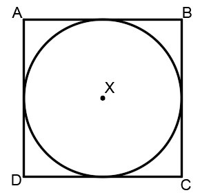
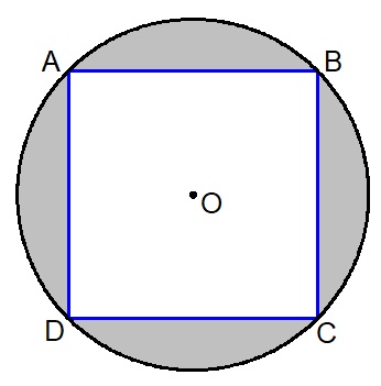
RC controllers sticks describe a square, while joysticks usually describe a circle. When this option is enabled a square is inscribed inside the joystick movement area to make it more like an RC controller (so it is possible to reach all four corners). The cost is decreased resolution, as the effective stick travel is reduced.

  • Disabled: When this is disabled the joystick position is sent to the vehicle unchanged (the way that it is read from the joystick device). On some joysticks, the (roll, pitch) values are confined to the space of a circle inscribed inside of a square. In this figure, point B would command full pitch forward and full roll right, but the joystick is not able to reach point B because the retainer is circular. This means that you will not be able to achieve full roll and pitch deflection simultaneously.

  • Enabled: The joystick values are adjusted in software to ensure full range of commands. The usable area of travel and resolution is decreased, however, because the area highlighted grey in the figure is no longer used.

Deadbands

Set that defines the function of the left and right sticks. This is normally set to mode 2.

provides a more detailed example of the default (mode 2) mappings for both Fixed Wing and Multicopter.

Press the Add Custom Action button. This will create a custom action item immediately above the button. Note at the button label is red, indicating that the assignment is incomplete or invalid. This will always be the case when a button is created.

Custom actions can be removed by selecting the red X marker at the end of the item.

Select the box then choose an action from the popup. Possible actions are .

By default the response to stick movement is linear (exponential=0). The exponential value makes the joystick less responsive in the middle of the range and more responsive on the edges - which can make it easier to fly.

Controls the frequency at which repeated button actions are sent (see tab)

Deadbands allow input changes to be ignored when the sticks are near their neutral positions. This helps to avoid noise or small oscillations on sensitive sticks which may be interpreted as commands, or small offsets when sticks do not re-center well. They can be adjusted during the first step of the , or by dragging vertically on the corresponding axis monitor.

Position Mode
calibration
mode
listed below
Button Assignment
General
Button Assignment
Circle correction enabled