## FAQ
### General
How do I get started with Auterion?
If your vehicle runs AuterionOS, start with the [Quickstart](/auterion-sign-up) guide and install the required software. To purchase Skynode hardware or for other inquiries, [contact the sales team](https://auterion.com/company/contact-us/).
Does Auterion offer paid support?
Yes. [Contact the Auterion sales team](https://auterion.com/company/contact-us/) to discuss support options.
### Technical Questions
How do I create a Skynode diagnostic report?
Open the vehicles [WebUI](/vehicle-operation/settings-and-maintenance/vehicle-dashboard) and navigate to **Diagnostics** → **Download Report**.
How do I factory reset a Skynode?
Open the vehicle's [WebUI](/vehicle-operation/settings-and-maintenance/vehicle-dashboard) and navigate to **Diagnostics** → **Reset**.
{% hint style="warning" %}
A factory reset removes all custom data and user applications, and clears the Auterion Suite activation.
{% endhint %}
How do I power Skynode S?
Skynode S supports two power input methods:
* USB-C interface
* ESC interface
{% hint style="warning" %}
Use the ESC interface to ensure connected peripherals receive sufficient power. Although Skynode S can boot from USB-C alone, this method does not provide enough power for peripheral devices.
{% endhint %}
How do I register a vehicle on Auterion Suite?
Complete the AMC Onboarding wizard to register your vehicle in Auterion Suite. See the [Quickstart guide](/auterion-sign-up) for full setup instructions.
Which version of AMC should I use?
Use the latest public release, available in the Suite Store and tagged as **Recommended**.
To ensure compatibility between AMC, AuterionOS, and APX4, refer to the **Bundles** section in the Suite Store.
How do I access AuterionOS via SSH?
Use the `ssh` command to connect to devices running AuterionOS. Default credentials are the same for all devices.
Device
IP Address
Username
Password
Development Connection
SSH Command
Password
Skynode
10.41.1.1
root
auterion
USB-C
ssh root@10.41.1.1
auterion
AI Node
10.41.2.1
root
auterion
micro-USB
ssh root@10.41.2.1
auterion
What programming languages do I need to know to develop apps?
Apps are generally developed using C++ or Python.
## Still have questions?
For questions about the software platform, partnerships, or to request a demo, contact us directly.
Contact us
#### If you have an Auterion Suite Account
With an Auterion Suite account, you can submit support requests and access product documentation under the [**Help and Support**](https://suite.auterion.com/help) menu in Suite.
# Quickstart
Set up your Auterion Suite account and register your first vehicle with Auterion Mission Control.
{% stepper %}
{% step %}
### Create a Suite account
Sign up
To create a new company account, select **Register for an Auterion account**. If you already have an account, select **Login**.
Complete the registration details and select **Create an Organization**.
{% hint style="warning" %}
Confirm that your organization does not already have a Suite account. If you are joining an existing account, contact your administrator and ask them to [invite you to Suite](/vehicle-operation/auterion-suite-fleet-management/administration/users).[](/vehicle-operation/auterion-suite-fleet-management/administration/users#invite-users)
{% endhint %}
After registration is complete, you will receive a welcome email. Follow the activation link in the email to activate your account.
{% endstep %}
{% step %}
### Register a vehicle in Suite
{% embed url="" %}
How to register a Freefly Astro in Suite
{% endembed %}
Registering your vehicle connects it to Auterion Suite. This allows you to access cloud features and manage your vehicle remotely.
1. Power on your vehicle.
2. Install Auterion Mission Control (AMC) from the Auterion store on your Ground Control Station (GCS). AMC is availible for Andriod, Windows, MacOS and
Install AMC
3. Complete the AMC [Onboarding wizard](/vehicle-operation/auterion-mission-control/navigating#onboarding-wizard-step-by-step).
4. AMC verifies LTE internet connectivity on your vehicle. If no connection is detected, enter your Wi-Fi details when prompted.
5. Once connected, select the registration link or scan the QR code to register your vehicle in Suite.
6. Log in to your Suite account when prompted.
7. In the pop-up window, select **Activate** to activate your Skynode. Your vehicle will then appear under **Fleet Management** → **Vehicles**.
8. In AMC, enable the cloud features: Live Telemetry, Image Upload, and Live Video via the Onboarding wizard.
Alternative Method to activate a vehicle in Suite
{% hint style="info" %}
If you are starting with a **Skynode Evaluation kit**, refer to [powering your Skynode](https://docs.auterion.com/hardware-integration/skynode/evaluation-kit/powering-skynode) for steps on how to power your Skynode.
{% endhint %}
1. Power on your vehicle.
2. Connect your vehicle to your computer via USB-C.
3. Navigate to the WebUI `10.41.1.1`.
4. Download and install AMC on your computer, then connect to your vehicle.
5. In AMC, navigate to the **Connectivity** tab and confirm your vehicle has an active internet connection.
6. In the WebUI dashboard, select **Activate Now** or scan the QR code.
7. When Auterion Suite opens, select **Activate** in the pop-up window. Your vehicle will appear under **Fleet Management** → **Vehicles**.
{% endstep %}
{% step %}
### Next Steps
{% endstep %}
{% endstepper %}
# Auterion Suite
[Auterion Suite](https://suite.auterion.com/) is a cloud-based web application for managing drone fleets, operations, and compliance at scale. It connects to vehicles running Auterion software via LTE or other network links and provides a central interface for fleet oversight, flight data, and reporting, accessible from the browser on a laptop or tablet.
{% embed url="" %}
{% hint style="info" %}
To start using Auterion Suite your company must first [sign up for an account](/auterion-sign-up).
{% endhint %}
## Key Capabilities
Create missions and synch them across your organization for anyone to use.
## How Suite Connects
Auterion Suite works best with vehicles running Auterion software via Skynode or compatible hardware. Vehicles connect to Suite over an internet-enabled link. AMC can be used alongside Suite for mission planning and in-flight control.
## Who Suite is made for
Program managers
Monitor fleet health, KPIs, and operational status via the Dashboard
Developers
Launch and connect to cloud-hosted Auterion Enterprise PX4 simulations
## Requirements
* An Auterion Suite account.
* Vehicles must have an active network connection to report live data.
{% hint style="success" %}
See our [website](https://auterion.com/enterprise/suite/) for more information about upgrading to **Auterion Suite Pro** or **Auterion Suite Enterprise**
{% endhint %}
# Fleet Management
Get up and running with Fleet Management in Suite.
Cover image
Dashboard
Keep an overview of fleet health, operations, and performance metrics
# Dashboard
Overview of fleet health, operations, and performance metrics in the Dashboard.
## Overview
The Dashboard provides an overview of fleet health and operations for a selected time period. All graphs reflect the **current time period**; percentage change indicators compare it to the **previous time period** of equal length. The `All Time` filter does not include percentage change.
{% hint style="success" %}
Hover over graphs to view additional detail.
{% endhint %}
### Definitions used in the Dashboard
* A **healthy flight** is one that did not report a Critical [flight status](/vehicle-operation/auterion-suite-fleet-management/fleet-management/flights#flight-status).
* A **compliant flight** is one where the pilot completed the [Preflight Checklist](/vehicle-operation/auterion-mission-control/ui-breakdown/vehicle-overview-menu/preflight-checklist).
* An **active vehicle** is one that was *armed* in the selected time period.
{% hint style="info" %}
The **Most Common Failures** graph reflects the most frequent reasons flights were marked as Critical. Use it to identify recurring failure patterns.
{% endhint %}
## Metrics Explained
### Fleet Health
Given a time range (default 3 months), fleet health is the percentage of flights that did not report a Critical flight status.
%↑ or %↓ is percentage change in the fleet health compared to a prior time window of the same size. The previous window may be smaller than the current window if data does not exist that far back in time.
### Number of Flights/Time/Distance
Cumulative values for a given time range are compared to the first value in the prior time range. These numbers include all flights, both success and failure.
%↑ or %↓ is calculated using the difference between first value in the prior time series and the current cumulative value.
### Active Vehicles
Active Vehicles shows the ratio of vehicles used in the selected time range to the total number of non-archived vehicles.
{% hint style="info" %}
If archived vehicles are flown, the active vehicle percentage may be greater than 100%.
{% endhint %}
# Vehicles
Review and manage the company's fleet
## Overview

The **Vehicles page** lists all vehicles registered to your organization, organized into vehicle groups.

Select a vehicle to view its **detail page**, including health status, flight summary, and maintenance information.
## Where to find common vehicle actions
| Action | Vehicle List (All vehicles) | Vehicle Overview (Single vehicle) | Manufacturer |
| ------------------------------------------------------------------------------------------------ | :-------------------------: | :-------------------------------: | :----------: |
| [**Register**](#register) | ✔ | | |
| [**Create**](#create) | | | ✔ |
| [**Group**](/vehicle-operation/auterion-suite-fleet-management/fleet-management/vehicles/groups) | ✔ | ✔ | |
| [**Rename**](#rename) | | ✔ | |
| [**Identity**](#identity) | | ✔ | |
| [**Update**](#update) | | ✔ | |
| [**Archive**](#archive) | ✔ | ✔ | |
| [**Restore**](#archive) | ✔ | ✔ | |
{% hint style="info" %}
Contact your Auterion Suite Administrator if any of the above options are not available.
{% endhint %}
## Activate a Vehicle
Activating your vehicle will connect it to Auterion Suite. This enables you to access cloud features and manage your vehicle remotely.
**To activate a vehicle:**
{% hint style="info" %}
If you are starting with a **Skynode Evaluation kit**, refer to [powering your Skynode](https://docs.auterion.com/hardware-integration/skynode/evaluation-kit/powering-skynode) for steps on how to power your Skynode.
{% endhint %}
1. Power your vehicle.
2. Connect your vehicle to your computer via USB-C.
3. Navigate to the WebUI `10.41.1.1`.
{% hint style="info" %}
To activate a vehicle make sure your vehicle is connected to the Internet using Auterion Mission Control > Connectivity tab.
{% endhint %}
2. Click **Activate now** or **Scan the QR code**.
3. You will be directed to Auterion Suite, where you'll see this pop-up window to activate your Skynode.
4. In Auterion Suite, select **Activate** in the pop-up window. Your vehicle will appear under **Fleet Management** → **Vehicles**.
## Rename a vehicle
1. Select a vehicle from the All Vehicles list.
2. Click **Rename vehicle** in the the toolbar next to the vehicle name.
3. Enter the new vehicle name in the pop-up and click on **Rename Vehicle** to confirm the change.
## Vehicle Identity
A vehicle consists of multiple components: an airframe, a Skynode, a flight controller, and more. Together, these components make up the vehicle's identity.
To view component serial numbers and IDs, click the **Vehicle identity** icon in the vehicle header.
This will open up a window that shows all of the IDs of the components that make up the vehicle in the Suite. Each ID controls a specific component. For example, the flight controller ID is how the logs coming out of a flight controller as associated with the vehicle page in the Suite.
{% hint style="success" %}
Manufacturers can use the vehicle identity modal to **modify** a vehicle's identity. This is useful when adding values during the manufacturing process or when building prototype hardware.
{% endhint %}
## Update a vehicle
1. Select a vehicle from the Vehicle List.
2. Click on the Software tab.
3. You'll find the available firmware versions for your Skynode.
{% hint style="warning" %}
Do not deploy updates to vehicles that are currently or scheduled to be deployed. Update in advance and in accordance with your particular drone program's guidelines.
{% endhint %}
## Archive / Restore
Archive and Restore are organizational tools for keeping the vehicle list focused on actively used vehicles.
**To archive a vehicle:**
1. Select a vehicle from the Vehicles list.
2. Click the **Settings** button (top right) and select **Archive**.
**To restore a vehicle:**
1. Navigate to **Vehicles** → **Vehicle Groups** → **Archived Vehicles**.
2. Select the vehicle you want to restore.
3. Click on Restore.
# Cloud Features
Enable and manage cloud-connected features for AuterionOS powered vehicles.
## Overview
Auterion Suite provides cloud-connected features for Auterion OS-powered vehicles, enabling real-time telemetry, live video, and automatic media upload from the field.
Auterion Suite includes the following cloud features:
* **Live telemetry:** View vehicle position and status on a live map.
* **Live video:** Stream a live video feed from the vehicle's onboard camera.
* **Picture upload:** Automatically upload photos taken during a flight.
{% hint style="info" %}
Cloud features require the vehicle to be activated in Auterion Suite before use. See [Activating a Vehicle](/vehicle-operation/auterion-suite-fleet-management/fleet-management/vehicles#register).
{% endhint %}
## Prerequisites
1. Connect the vehicle to a cellular or Wi-Fi network with internet access. For Wi-Fi setup instructions see [Connectivity in AMC](/vehicle-operation/auterion-mission-control/ui-breakdown/vehicle-overview-menu/connectivity).
2. Connect your computer to the vehicle via USB-C and open the vehicle's WebUI at `http://10.41.1.1` .
## Enable Cloud Features
# Groups
Sort and organize your vehicles
## Overview
Default groups
Groups let you segment your vehicle fleet into named collections. Use groups to filter the vehicle list, track fleet status at a glance, and manage vehicles by team, project, or location.
By default, Auterion Suite includes two system groups that cannot be deleted:
* **All vehicles:** Displays every active vehicle in the organization. This view is identical to the default vehicle list.
* **Archived vehicles:** Displays all archived vehicles.
## Create a Group
1. Navigate to **Fleet Management** → **Vehicles**.
2. Select **+ New Group**.
3. Enter a **Name**. This appears on the Vehicle Groups panel.
4. Enter a **Tag**. The tag displays in the vehicle list rows and on the vehicle page when space is limited.
5. To set a custom color or icon, select the logo at the top of the dialog.
6. Select **Create**.
The new group appears in the Vehicle Groups panel.
## Adding and removing vehicles
{% tabs %}
{% tab title="From the vehicle list" %}
1. Navigate to **Fleet Management** → **Vehicles**.
2. Hover over a vehicle row and select **Join Group** in the **Groups** column.
3. In the **Manage Vehicle Groups** dialog, select the groups to add the vehicle to.
4. Select **Done**.
{% endtab %}
{% tab title="From a vehicle page" %}
1. Open the vehicle page.
2. Scroll to the **Vehicle groups** section.
3. Select the pencil icon to open the **Manage Vehicle Groups** dialog.
4. Select the groups to add or remove the vehicle from.
5. Select **Done**.
{% hint style="info" %}
The **Manage Vehicle Groups** interface is the same whether accessed from the vehicle list or a vehicle page. All groups are listed, and a vehicle can join or leave any group from either location.
{% endhint %}
{% endtab %}
{% tab title="From a group" %}

1. Open the group page.
2. Search for a vehicle by serial number (SNO) and select it to add it.
{% hint style="info" %}
To remove a vehicle, hover over it in the **Manage group** window and select the red **×**.
{% endhint %}
{% endtab %}
{% endtabs %}
# Assets
Asset Management lets you track all hardware associated with your fleet, including payloads, controllers, batteries, and SIM cards, whether added manually or created automatically by Auterion Suite.
## Overview
With Asset Management, you can manage all assets in your organization, whether they were automatically created by Suite (for example from a flight log upload) or manually added by a user.
With Asset Management, you can manage all assets in your organization, whether they were automatically created by Auterion Suite (for example from a flight log upload) or manually added by a user.
Vehicle SIM cards are also managed as assets in Auterion Suite, which can track SIM data usage and monitor progress toward the monthly data allowance.
### How assets are defined in Suite
In Auterion Suite, assets are defined by three properties: **type**, **assignment**, and **creation method**.
Asset types
When you create an asset, you select its **type** (for example payload, controller, battery, SIM card). The type controls how the asset is displayed and grouped in Suite.
How assets are assigned to vehicles
* **Dedicated to a vehicle**: The asset is linked to a single vehicle and will be automatically recorded on flights taken by that vehicle.
* **Shared between vehicles**: The asset can be assigned to multiple vehicles in your organization and will not be recorded unless assigned preflight.
How assets are created
* **Automatically created assets** are created by Suite and always dedicated to one vehicle (for example, a detected SIM card).
* **Manually created assets** are added by the user and can be set as either dedicated or shared, such as payloads or other equipment you want to track. In the next section we will see how to create these assets.
## Creating an Asset in Suite
To manually add an asset in Auterion Suite:
1. On the **Assets** page, select **Add Asset** in the top-right corner.
2. In the pop-up, enter a **name**, choose an **asset type**, and select whether the asset is **dedicated to a vehicle** or **shared**.
3. (Optional) For better tracking, add the **model**, **manufacturer**, and **serial number**.
4. Click **Save**.
#### Assigning assets after creation
* For **dedicated assets**, open the relevant **vehicle page**. You will be prompted to assign the dedicated asset to a vehicle.
* For **shared assets**, you can assign the asset to one or more vehicles from the **vehicle page**, as described in[#assigning-assets-to-vehicles](#assigning-assets-to-vehicles "mention").
## **Viewing and editing asset details**
To view more details about an asset, click it in the Assets table. This opens the asset detail page, which shows tracked flights, notes, and, for batteries, battery health information.
### Edit an Asset
To edit an asset:
1. Click the **edit icon** in the Assets table, or select **Edit Asset** on the asset detail page.
2. Update the required fields in the dialog.
3. Click **Save**.
{% hint style="warning" %}
Automatically created assets are always dedicated to a vehicle, so you cannot change them from dedicated to shared.
{% endhint %}
### Assign Assets to Vehicles
1. In the asset page under Asset Overview click the pen icon.
2. In the pop-up select the vehicle(s) you want to assign the asset to.
3. You can also remove vehicles by clicking on the X next to their name.
4. Click Done to confirm.
5. In the vehicle page under Assets click the pen icon.
6. In the pop-up select the asset(s) you want to assign to the vehicle.
7. You can also remove assets by clicking on the X next to their name.
8. Click Done to confirm.
To assign a shared asset to one or more vehicles, use one of the following methods.
{% tabs %}
{% tab title="From the asset page" %}
1. In the asset page under Asset Overview click the **pen icon**.
2. In the pop-up select the vehicle(s) you want to assign the asset to.
3. You can also remove vehicles by clicking on the X next to their name.
4. Click **Done** to confirm.
{% endtab %}
{% tab title="From the vehicle page" %}
* In the vehicle page under Assets click the **pen icon**.
* In the pop-up select the asset(s) you want to assign to the vehicle.
* You can also remove assets by clicking on the X next to their name.
* Click **Done** to confirm.
{% endtab %}
{% endtabs %}
### Add Notes to an Asset
Add notes to an asset to record issues, maintenance actions, or usage context. Notes are created and viewed on the asset’s detail page and remain tied to that specific asset, making it easier to track its history over time.
To create a note:
1. Open the asset’s detail page in Auterion Suite.
2. Go to the **Notes** tab.
3. Select **Add note**.
4. Enter your note and click **Create**.
All notes for that asset are listed in the **Notes** tab.
# Flights
View and manage flight records for all vehicles in your organization.
## Overview
The flight list shows all flights recorded by your organization's vehicles. Use the controls at the top to sort and filter the list. Three preset views are available: **Operator**, **Developer**, and **Custom**. Access the flight list from the main menu, or from a specific vehicle's overview page.
### Log upload status
In the flight list two indicators may appear next to the flight start time:
Cover image
Red dot: Log upload issue (timeout waiting for log data - about 10 minutes).
{% hint style="danger" %}
Log upload failures typically occur when the vehicle is powered off immediately after landing before the upload completes. Other causes include poor connectivity, inactive data plans, or hardware issues such as loose wiring.
{% endhint %}
### Flight Status
The *Flight Status* is used to highlight any problems detected by *flight analysis*. *Auterion Suite* reports the following status values:
* **Healthy:** Flight completed with no issues.
* **Warning:** Flight completed successfully, but a non-critical issue was detected.
* **Critical:** Flight terminated with a critical issue reported (it may have crashed).
{% hint style="info" %}
The **Fleet health** indicator on the [Dashboard](/vehicle-operation/auterion-suite-fleet-management/fleet-management/home) reports all non-Critical flights as "Healthy".
{% endhint %}
## Reviewing a flight
Access a flight record from either of the following locations:
* The main **Flight List.**
* The **Flight List** within a vehicle's **Vehicle Overview.**
This page will show all of the data associated with a flight. Each flight record includes:
* High-level summary information about the flight
* Vehicle used for the flight
* Operator who controlled the vehicle
* Attached files, images, notes, and logs
### Flight Logs
Flight logs are available for review on the **Logs tab** of the flight page.
The **Logs** tab displays a summary of all automated checks run against the flight log. For deeper analysis, click **Open Analytics**.
{% hint style="warning" %}
Flight logs will only be uploaded if you are using an Auterion powered vehicle.
{% endhint %}
#### Flight Log Analytics
The analytics page provides a detailed breakdown of all data collected during a flight.
Each analyzed metric displays a colored icon in the corner of its panel:
* **Green:** Pass
* **Yellow:** Warning
* **Red:** Failure
Metrics without an icon have not been analyzed.
{% hint style="success" %}
The analytics toolset is updated regularly. To ask about a specific metric or request a new one, [contact](https://auterion.com/company/contact-us/).
{% endhint %}
#### Downloading Flight Logs
Download flight logs for compliance reporting, post-flight analysis, or integration with third-party tools. Logs can be downloaded from two locations:
{% tabs %}
{% tab title="Flight → View Log Analytics → ..." %}
{% endtab %}
{% tab title="Flight → Logs → ..." %}
{% endtab %}
{% endtabs %}
Depending on your Suite subscription you can download following formats of your logs:
Type
Description
Usecase
Suite Tier
ULog File Format
Raw data as recorded by the vehicle.
In-depth technical analysis using tools such as Flight Review, PlotJuggler, or custom scripts. Required for advanced debugging and vehicle tuning.
Archiving flight records, or submitting logs to Auterion support for diagnostics.
All tiers
Compliance CSV
Limited export of flight data.
Regulatory reporting, audit trails, and insurance documentation. Suitable for submitting flight records to civil aviation authorities.
All tiers
GUTMA flight logging format
Global UTM Association flight logging format export.
Sharing flight data with UTM providers, authorities, or third-party fleet management platforms such as Airdata or DroneLogbook. Designed for interoperability across the UTM ecosystem.
All tiers
# Compliance
Export flight records to demonstrate that operations have been properly conducted.
The **CSV** button in the top-right corner of the Flights list exports all flight data matching the active filters and displayed columns.
## Configure and export reports
### Configuration
#### Select and order your columns
1. Choose "Custom" from the column selector (first button in the toolbar).
2. Select and order the custom display using the settings button that appears on the column selector
#### Filter by specific dates, pilots and vehicles
* Use the **Time Frame** filter to narrow the date range.
* Select a single vehicle or pilot for more focused reporting.
#### Order by date or value
The sorting shown in the UI will be the same sorting used when downloading a report. Click a column header to sort by that value before exporting.
### Export
Once filters, sorting, and columns are configured, click **CSV** in the top-right corner to export the report.
# Fleet Deploy
Fleet deploy provides a way for Suite users to install + update applications and firmware on multiple vehicles fleet-wide. After selecting an eligible software product along with an available release and one or more vehicles, users can queue a deployment- the specified product will then be installed on the included vehicles over the air.
### Requirements For a Deployment
* **OTA** installation must be enabled for vehicles intended to be used in a deployment - this is defined on a **vehicle model** basis and needs to be set by the manufacturer via the [Vehicle Models](https://suite.auterion.com/manufacturer/models) tab.
In order to construct a fleet deployment, the following must be true:
* The release for the target product to be deployed must be set as **available** by its manufacturer. The release *cannot* be vehicle-specific, (i.e. a release that applies to one or more *individual* vehicles).
* If the target product is **licensed**, a license must be assigned to all vehicles intended to be included in the deployment.
{% hint style="info" %}
The requirements above are also summarized in the **Fleet Deploy** page info tooltip, pictured below.
{% endhint %}
### How to Queue a Deployment
1. To queue a deployment, navigate to the [Fleet Deploy](https://suite.auterion.com/fleet-deploy) page under **Fleet Management**.
2. Select the **‘+ New Deployment’** button in the top right corner to navigate to the [deployment builder](https://suite.auterion.com/bulk-release-deployments/create).
3. Select the **product**, **release** and set of **vehicles** to be included in the deployment. If you do not see a product, release, or vehicle option you are expecting, check the requirements [above](https://www.notion.so/Fleet-wide-Operations-2159af1fb77f80a5ba16f3767b649705?pvs=21) to ensure the component is valid.
4. Click **Queue Deployment**. The specified product release will now be deployed to each of the selected vehicles the next time they come **online**.
{% hint style="info" %}
**Note**: An individual vehicle release deployment will remain **pending** until the vehicle comes **online**.
{% endhint %}
## Viewing Deployment Statuses
You can view the status of queued fleet deployments via the **Active** and **Finished** tabs on the [Fleet Deploy](https://suite.auterion.com/fleet-deploy) page.
### Active Deployments
**Active** deployments are listed in the [Active](https://suite.auterion.com/bulk-release-deployments?tab=active) tab. Users can view the **product** deployed, **time** that the deployment was triggered, and completion progress within each entry. Additionally, hovering on the info ℹ️ icon will display a list of vehicles and their respective deployment statuses.
#### Finished Deployments
**Completed** deployments are listed in the [Finished](https://suite.auterion.com/bulk-release-deployments?tab=finished) tab. Users can view **product** deployed, **time** of deployment completion, and a summary of the resulting deployment (counts of `deployed`, `cancelled`, and `failed` vehicle deployments). Like the active deployment list, hovering on the info ℹ️ icon will display a list of vehicles and their respective deployment statuses.
### Canceling Deployments
At this time, cancelation can only be done on a *vehicle by vehicle* basis- users must navigate to an individual vehicle’s **Software** tab, locate the target product, and click the **Cancel** button.
{% hint style="info" %}
**Tip**: Individual vehicle software pages are linked within the vehicle deployment status info popover within a deployment entry for easy navigation.
{% endhint %}
{% hint style="info" %}
The cancelation steps are also summarized in the **Fleet Deploy** page info tooltip, pictured below.
{% endhint %}
# Mission Planning
The features described in the following pages are designed to assist the user planning autonomous missions and optimising their outcome.
# Mission Cloud Sync
## Overview
**Mission Cloud Sync** allows pilots and mission planners to sync missions between **AMC (Auterion Mission Control)** and the **Auterion Suite**. Missions created on any AMC device are automatically available to all pilots in your organization through Auterion Suite.
Use Mission Cloud Sync to:
* Plan missions remotely and make them immediately available to field pilots.
* Apply standardized missions across multiple compatible vehicles.
* Allow pilots to make on-site adjustments to adapt missions to local terrain conditions.
Once a mission is uploaded to the Auterion Suite, pilots can download and execute it directly from AMC at the mission location.
## Setup
1. Download AMC and ensure the device running AMC has an active internet connection.
2. Log in to your Auterion Suite account in AMC by clicking **Log in** in the side menu.
3. In AMC, go to the **Quick menu** → **Cloud.**
4. Locate **Enable Mission Cloud Sync for missions** and confirm the toggle is enabled.
### Accessing your missions
Once Mission Cloud Sync is enabled, all missions stored in your organization's Auterion Suite are available in AMC.
1. Open the **Plan** menu in AMC.
2. Select **Missions** from the top bar.
The connection status to the Auterion Suite is shown in the top-left corner of the Missions panel. A green indicator confirms an active connection.
{% hint style="info" %}
For more on how to create mission visit [Mission Menu](https://docs.auterion.com/vehicle-operation/auterion-mission-control/ui-breakdown/plan/plan-tools/mission-menu).
{% endhint %}
While connected to the Suite, any new mission you save, or any changes to an existing mission, are automatically stored in the Auterion Suite.
### Managing Missions in Auterion Suite
Auterion Suite is the central location for storing, organizing, and managing all missions across your fleet. To access your missions in the Suite:
1. Log in to your Auterion Suite account via a web browser.
2. Navigate to **Operations** → **Mission Synch**.
**From the Missions page you can:**
* View all missions synced from AMC in list format
* Select a mission to preview its flight path or survey area on the map
* Download or upload missions locally as `.plan` files
* Add missions directly using **Add Mission**
# Preflight Checklist
## Overview
Preflight checklists help teams standardize flight preparation and ensure every mission starts with the same safety and compliance steps. In Auterion Suite, you can build checklists using an editor and deploy them to your fleet. Checklists appear in Auterion Mission Control (AMC) when a pilot connects to a vehicle.
## Before You Start
#### Prerequisites
* Auterion Suite with an active **Enterprise** subscription.
* A Ground Control Station (GCS) running **AMC v1.39.7 or later.**
* Pilot Profile logged in on the GCS.
{% hint style="info" %}
This feature is also available on **AMC v1.38.0** using a JSON file. See [Preflight Checklists (AMC v1.38.0)](#creating-a-checklist-using-a-json-amc-1.38.0) for instructions.
{% endhint %}
***
## Create a checklist
1. In Auterion Suite, go to **Fleet Management** → **Compliance** → **Preflight Checklists**.
2. Select **Create**.
3. Enter a **Checklist Name**. This name is only visible in Suite.
4. Enter a **Display Title**. This is the title pilots see in AMC.
5. In **Vehicle Group**, select the [group](/vehicle-operation/auterion-suite-fleet-management/fleet-management/vehicles/groups) of vehicles this checklist applies to. If no group is selected, the checklist applies to all vehicles registered in Suite.
6. Configure the following options as needed:
Toggle
Description
Set as active checklist
This checklist becomes active only for the chosen group and will replaces any other active checklist assigned to that group.
Enforce checklist completion
All required checks must pass before the vehicle can be armed.
Auto-open on connect
Opens the preflight checklist menu in AMC when a pilot connects to a vehicle.
### Adding checklist steps
Checklists are organized into checklist groups. Each checklist group acts like a section in AMC and contains one or more check items.
1. Select **+ Add Group**.
2. Enter a **Group Title.** This is the group title displayed in AMC.
3. Drag items from the **Components** panel on the right into a group.
* **Automated Checks:** Pass/fail status is determined automatically by the vehicle (for example, Battery, GPS, Sensors Health).
* **Manual Checks:** Requires the operator to manually confirm a custom checklist item. The title and description are configurable.
4. To reorder groups or checks, drag using the handle on the left of each item.
To mark a check as mandatory, enable the **Required** toggle on that item. Required checks must be completed before the checklist can be passed.
{% hint style="info" %}
Some automated checks have configurable thresholds. For details, see [Checklist Components](#checklist-components).
{% endhint %}
### Deploy the Checklist
1. Enable **Set as active checklist** for the selected vehicle group.
2. Select **Save**.
The checklist deploys to all vehicles in the group. Pilots will see it in AMC under **Quick Settings** → **Preflight Checklist** the next time AMC connects.
To change the active preflight checklist, go to **Fleet Management** → **Compliance** → **Preflight Checklists** and enable the desired checklist.
### Using the Checklist in AMC
The checklist is accessible from **Quick Settings** → **Preflight Checklist** (or the configured checklist name).
* **Automated checks:** Pass or fail automatically without operator input. Automated checks are labelled **Auto** in AMC.
* **Manual checks:** The operator manually confirms each item.
To restart the checklist, select **Reset** in the top-right corner.
Label
Description
Symbol
Required
Mandatory check configured in Auterion Suite. The vehicle cannot be armed until this check passes.
Optional
Check is not mandatory. The vehicle can be armed even if this check does not pass.
Auto
Pass/fail status is determined automatically by the vehicle. No pilot input required.
{% hint style="warning" %}
If **Enforce checklist completion** is enabled, the vehicle cannot be armed until all required checks are passed.
{% endhint %}
***
## Checklist components
Symbol
Name
Description
Airspeed Sensor (Requires user input)
Prompts the operator to confirm that the airspeed sensor is attached and free from dirt, and that the displayed airspeed value changes when the sensor is blown into.
Battery
Checks vehicle battery level. Requires >80% charge by default. The threshold can be adjusted in Suite.
Battery Controller
Checks GCS/controller battery level. Requires >80% charge by default. The threshold can be adjusted in Suite.
Actuators
Moves all servos and prompts the operator to confirm that all control surfaces responded correctly. Verifies both control surfaces and tilt actuation by default. Configure in Suite to verify control surfaces, tilt actuation, or both.
GPS Fixed-Wing Landing
Checks that the GPS fixed-wing landing application is installed and running on the vehicle.
GPS
Checks for an active GPS lock. Requires more than 3 satellites and a 3D fix by default. The threshold for the number of satellites can be adjusted in Suite.
RC Controller
Checks for a connected and calibrated controller. Accepts any controller type by default. Can be restricted to RC only or joystick only in Suite.
Sensors Health
Checks that required onboard sensors are healthy. If any of the sensors are unhealthy, one of the following messages is displayed:
Failure. Magnetometer issues. Check console.
Failure. Accelerometer issues. Check console.
Failure. Gyroscope issues. Check console.
Failure. Barometer issues. Check console.
Failure. Airspeed sensor issues. Check console.
Failure. AHRS sensor issues. Check console.
Failure. GPS sensor issues. Check console.
Sound
Checks that the Ground Control Station buzzer and audible alerts are operational.
Camera Storage (manual check)
Checks that the camera is plugged in and has adequate free space. This is a manual check. The operator confirms visually.
System Health
Reports the vehicle's Health and Arming check status. Reports the first problem found and the total number of problems.
Video Stream Quality - EO
Checks video quality in Electro-Optical range with thresholds:
FPS threshold : Minimum frames-per-second required for the check to pass.
Max Artificial Rate (%) : Maximum allowed artifact rate (percentage) before the check is failed.
Video Stream Quality - IR
Checks video quality in Infrared range with thresholds:
FPS threshold : Minimum frames-per-second required for the check to pass.
Max Artificial Rate (%) : Maximum allowed artifact rate (percentage) before the check is failed.
Parachute
Checks that the parachute system is connected and ready for use.
Mission
Checks that a valid mission is uploaded to the vehicle and can be started.
Dual Radio
Checks for two active radio links and ensures redundant (primary/backup) connectivity.
Single Radio
Checks for a single active radio link.
Computer Temperature
Checks Computer temperature.
Engine
Engine check with following adjustable parameters:
Test throttle (%) : Throttle percentage sent to the motor during the test.
Test duration (s) : Motor command timeout in seconds; the test auto-stops when this elapses.
Expected RPM : RPM threshold for auto pass/fail. If the peak RPM observed during the test reaches this value the check passes; otherwise it fails.
Expected Amperage : Amperage threshold in A for auto pass/fail. If the peak battery current observed during the test reaches this value the check passes.
Manual (Customizable, requires user input)
Custom manual check. The title and description are configured in Auterion Suite. Requires operator input.
***
### Creating a Checklist using a JSON (AMC 1.38.0)
Create a JSON file and upload it directly to Auterion Suite or AMC. This method is supported on **AMC v1.38.0** and later.
Creating a Checklist using a JSON
**You Need**
* Auterion Suite with an active **Enterprise** subscription.
* A Ground Control Station running **AMC v1.38.0 or later and logged** in with your Pilot Profile.
## Checklist File Structure
Preflight checklists are structured into **main titles**, **groups**, and **individual steps**. Each step includes a **title** and **description**. You define these titles, groups, and steps in your checklist.
**Template:**
```json
{
"mainTitle":"Auterion",
"groups":[
{
"title":"Group 1",
"preflightCheckList":[
{
"title":"First check",
"description":"Description of first check"
},
{
"title":"Second Check",
"description":"Description of second check"
}
]
},
{
"title":"Group 2",
"preflightCheckList":[
{
"title":"First check of group 2",
"description":"Description of first check of group 2"
},
{
"title":"Second Check",
"description":"Description of second check of group 2"
}
]
}
]
}
```
### Creating a checklist using a JSON
**Field Description:**
1: `mainTitle` – Defines the title in the pre-flight checklist overview.
2: `title` – Defines the title in the pre-flight checklist group within `groups` .
3: `title` – Defines the title of the checklist step within `preflightChecklist` .
4: `description` – Defines the description of the checklist step within `preflightChecklist` .
**Example:**
```json
{
"mainTitle":"Auterion Pre-flight Checklist v0.0.1",
"groups":[
{
"title":"Weather Check",
"preflightCheckList":[
{
"title":"Check Rain",
"description":"Please check for rain in the area"
},
{
"title":"Check Clouds",
"description":"Please check for cloud cover"
}
]
},
{
"title":"Equipment",
"preflightCheckList":[
{
"title":"Propellers Check",
"description":"The propellers are in good condition and ready for flight."
},
{
"title":"Battery Check",
"description":"The battery is fully charged and ready for flight."
}
]
}
]
}
```
Save your file with the extension `.json` (for example, `preflight.json`). You’ll upload this file in the next step.
## Activating Preflight Checklists
### Through Auterion Suite
1. **Go to Fleet Management** → **Compliance** →
2. Under the Preflight Checklist section click Create **→ Import**
3. In the dialog, enter a **checklist name** (this name is only shown in Suite).
4. Click **Select File** and upload your **checklist JSON**.
5. Review the file in the preview window, then click **Add**.
6. To enable the checklist for your entire fleet, toggle it to **Active.**
#### Through AMC
{% hint style="warning" %}
Activating the Preflight checklist in AMC enables it for that vehicle only.
{% endhint %}
1. Ensure your checklist file name ends with **`.preflightCheckList`** (for example, `myChecklist.preflightCheckList`).
2. Open **AMC**.
3. In the side menu, go to **Settings** → **General**.
4. In **Preflight checklist**, use **Upload** to select and upload your JSON file.
{% hint style="info" %}
You can download the JSON of any checklist created in Auterion Suite by selecting the preview icon and choosing **Download JSON**.
{% endhint %}
### Settings
The **Preflight Checklist** section in AMC includes the following options:
* **Import / Remove**: This is how you manage the Import or removal of the Preflight checklist from the vehicle.
* **Refresh:** Ensures AMC is using the latest preflight checklist from Suite.
* **Skip Default Preflight Checklist:** Disables the default vehicle checklist so you can focus on your imported checklist.
* **Require Preflight Checklist to pass before arming:** Requires the imported checklist to be completed before the vehicle can be armed.
* **Automatically open Preflight Checklist:** Opens the preflight checklist automatically when AMC starts.
***
## Settings
In AMC, go to **Settings** → **Preflight Checklist**.
* **Refresh Suite Preflight Checklist:** Syncs AMC with the latest active preflight checklist from Auterion Suite.
* **Require Preflight Checklist to pass before arming:** When enabled, the preflight checklist must pass before the vehicle can be armed.
# For Manufacturers
Cover image
Service Bulletins
Communicate updates and notices to your users by publishing service bulletins.
# Service Bulletins
### How Service Bulletins Work
Service bulletins provide a means for communicating important updates or notices to users. These bulletins can be created, reviewed, and published using this feature. Below is an explanation of the lifecycle and the states a service bulletin can transition through.
You can manage service bulletins using both the Dashboard and the API.
### State Transition
After creation, service bulletins move through a series of statuses. Each status defines what actions are possible and how the bulletin is handled. The lifecycle looks like this:
| **State** | **Description** | **Possible Actions** |
| -------------------------------- | ---------------------------------------------------------------------------------------- | ----------------------------- |
| **Draft** | The service bulletin is open for editing and review. | Preview and Schedule Publish. |
| Publish Now. | | |
| Send Test Emails. | | |
| **Preview and Schedule Publish** | The bulletin is locked for editing and will be published at the end of the grace period. | Revert to Draft. |
| Publish Now. | | |
| Send Test Emails. | | |
| **Published** | The bulletin has been published, and notifications have been sent. | No further actions. |
### State Descriptions and Rules
#### Draft
* **Description:**
* The bulletin is open for editing and review.
* **Actions:**
* Preview and Schedule Publish: Locks the bulletin for editing and schedules publication after a 1-hour grace period.
* **Publish Now**: Immediately publishes the bulletin and sends user notifications.
* Send Test Email: Send a test email to review the service bulletin before publication.
#### Preview
* **Description:**
* The bulletin is locked for editing and scheduled for automatic publication.
* **Rules:**
* No edits or deletions are allowed.
* **Actions:**
* **Revert to Draft**: Cancels the scheduled publication and unlocks the bulletin for further edits.
* **Publish Now**: Immediately publishes the bulletin and sends notifications.
* end Test Email: Send a test email to review the service bulletin before publication.
#### Published
* **Description:**
* The bulletin has been published and notifications sent.
* **Rules:**
* The bulletin is locked; no further actions or edits are allowed.
* **Actions:**
* None.
### Usage Example
#### Creating a New Bulletin
1. Start by creating a bulletin in the **Draft** state.
2. Edit and review the content.
#### Publishing a Bulletin
* Use **Publish with Preview** to lock the bulletin and schedule it for publication after a 1-hour grace period.
* Use **Publish Now** to immediately publish the bulletin.
#### Managing Preview State
* If changes are required during the 1-hour grace period, use **Revert to Draft** to cancel the scheduled publication and unlock the bulletin.
* If ready to publish immediately, use **Publish Now**.
#### Post-Publication
* Once published, the bulletin is locked, and no further actions are available.
# Suite Manufacturer Tools
Auterion offers software and hardware to assist with all stages of the manufacturing process. These workflows are designed to facilitate easy verification of the Skynode platform as well as assisting with vehicle sales and vehicle configuration once in customers' hands.
## How to get access?
To get access to the Manufacturer section it is necessary to have an active Auterion Company Account. If you do not yet have one, please follow the [Auterion Sign-up guide](/auterion-sign-up).
Once you have an active account sign in to [Auterion Suite](https://suite.auterion.com/) and navigate to the Administration tab's "Plan, Billing & Usage" page where you can request access to the Manufacturer section and its tools.
## Auterion-enabled Workflow
1. **Create a model** from an existing Skynode.\
Once created, you can change the model settings by clicking on the edit icon under the "Actions" column of the models page. These changes are required before selling the vehicle to end-users.
Create a model
Change your model settings, by clicking on the edit icon
#### Change model settings:
* **Display Name** - Vehicle model name that appears in Auterion Suite
* **Support Email** - Your company's support email address, notifications for logs are sent here
* **Support URL** - Your company's support page, shown in your customers' Help & Support section
* **Explore URL** - Your company's website
* **Show in Registration** - If enabled, the vehicle will be available for the customer to activate
* **Allow OTA Updates** - If enabled, allows over-the-air software updates
Model Settings
2. **Activate your Skynode**
Your model in the Suite
3. **Create a Vehicle based on a Model**\
Vehicle creation is the process of recording the newly manufactured vehicle in Auterion Suite with the following details:
* Give a vehicle name
* Select a vehicle model
* Add a vehicle serial number
* Select an active Skynode
{% hint style="info" %}
This association will create a new vehicle record which a customer can later register and use in Auterion Suite.
{% endhint %}
Create a vehicle
4. **Unlocking for Sale**\
When production of a vehicle is finished and the vehicle is ready to be sold, it must be **unlocked for transfer.** A vehicle can be unlocked from the vehicle list, or directly through the[ Cloud SDK.](https://api.auterion.com/docs/)
Allow transfer
{% hint style="info" %}
Vehicles cannot be claimed and transferred without first being unlocked. This final step protects the vehicles and your future customers from incorrect association or registration.
{% endhint %}
5. **Customer Registration**\
Once customers receive their new vehicles, they can use the [**quickstart**](http://suite.auterion.com/quickstart) setup tool to automatically detect and register them. Upon registration, vehicles will be transferred to the customers' accounts, from the manufacturer's account. Customers can then use and manage their new vehicles.
{% hint style="info" %}
The manufacturer has access to all flight logs that have been "Shared with the manufacturer" through the Support tab.
{% endhint %}
# Administration
Cover image
Suite Settings
Manage the Suite plan and settings for the entire company
# Settings
Manage the Suite plan and settings for the entire company
{% hint style="danger" %}
At this time, settings are available to **Administrators only**.
{% endhint %}
Suite Settings includes control of:
* [Account & Usage](#account-and-usage): Keep an overview of your usage, licenses and add account features.
* [Plan & Billing](#plan-and-billing): Manage your Auterion Suite plan, upgrade, and change billing details.
* [User Management](#user-management): Invite and manage users.
* [API Key Management](#api-key-management): Control keys for direct integration with the Suite.
## Account & Usage
Besides an overview of your account and setting your System Notification email you can check:
### Account Status
Usage
Review the current **number of seats** you have in your plan, the current number of **seats being used**, and modify the number of seats in your plan.
{% hint style="info" %}
The total monthly bill is equal to the **monthly rate** \* the number of **seats purchased**
{% endhint %}
Licenses
* **Licenses:** Shows total licenses and how many are used.
* **View licensed vehicles and assets:** Opens the list of assigned vehicles (which vehicle/asset is using which license).
### Account Features
Here you can join the **App Developer Program**, which gives you access to the tools you need to build apps for **AuterionOS**, as well as **Manufacturer Tools**. To learn more, see:
Cover image
App developer program
Join the developer program and build custom applications for AuterionOS.
## Plan & Billing
The **Plans** section allows the current plan to be viewed and changed.
### Billing
If you need to **change your billing information/payment method**, click **Change Billing Details**. Your payment card can be changed at any time.
{% hint style="danger" %}
Companies using the Suite with custom pricing or invoice-based pricing will not have the ability to set a credit card.
{% endhint %}
{% hint style="info" %}
All payment processing and credit card information is securely handled by [Stripe](https://stripe.com/).
{% endhint %}
### Changing Suite Plan
In the Explore Plans section you can select a different Suite plan.
Each plan provides an overview of the features you will activate with your subscription. Upgrading to a paid plans requires a card to be on file.
Please take note that:
* **Upgrading** **a plan** will immediately upgrade the account and bill the registered card.
* **Downgrading the plan** will immediately credit the account and step down to a lower plan.
* **Canceling a paid plan** is done by downgrading to Basic
## User Management
To learn more about user management please refer to our dedicated documentation page:
***
## API Key Management
Documentation of the API methods and availability can be found at [api.auterion.com/docs](https://api.auterion.com/docs)
### Creation
To create a new API Key:
1. Navigate to *Administration* and select the *API Keys* tab
2. Click the "Add API Key" button
3. Optionally add a name\
\&#xNAN;*Note: Names do not impact the functionality of the key, but make it easier to the intent of a key.*
4. Create the key
Once a key is created, you will be shown the following dialog. This is the **only time** that the full key will be viewable, but **new keys can be created at any time.**

### Deleting/Deactivating Keys
Click the "Delete API Key" button on an individual API Key. The key will be immediately deactivated and the API will reject any further requests made with that key.
# User Management
Inviting new users, and supporting existing ones
## Invite Users
1. **As an Administrator**, click "Invite users"
2. Enter the email(s) to invite, and set their default group
3. Click "Send invites"
4. Users will be sent an invite that must be accepted to use the Suite
5. Once an invite is accepted the user will be shown in the user list, and will be considered towards plan seats
## Accept an invite
1. Locate the invitation email:
* **Sender:** **
* **Subject line:** (similar to) "You have been invited to company \ at Auterion Suite"
2. Click **Create Account** in the email to open the account creation form
3. Complete the account creation form and submit
4. Log into the Suite
## Groups
Groups (roles) are displayed on the user entry, along with their email address and name. To edit a user's groups:
1. Select the "Change groups" button on the user record
2. Select all the required permissions
3. Click **Save**
{% hint style="danger" %}
Users can only upgrade another users's permissions to their own level.
{% endhint %}
## Activate/Deactivate
User accounts can be activated or deactivated by finding the account under the proper tab and selecting the action from the available actions.
To deactivate a user:
1. Select the active tab
2. Find the user
3. Click "Deactivate"
4. Confirm the action
User activation (after having been previously deactivated) is the same.
# Auterion Mission Control
[Auterion Mission Control](https://auterion.com/mission-control/) is a powerful and fully featured ground control station application that is optimized for **pilots** of Auterion-powered vehicles.

{% hint style="info" %}
Auterion Mission Control on the ground is constantly connected with Auterion Enterprise PX4 on the drone and Auterion Suite in the cloud. Mission Control allows you to operate any drone powered by Enterprise PX4 and puts the tools that pilots need most "front-and-center": safety checklists, flight controls, mission planning and payload control.
{% endhint %}
**Auterion Mission Control (AMC)** is the central interface for modern autonomous operations. It provides a comprehensive suite of tools designed to ensure every flight is safe, compliant, and efficient — from initial planning to touchdown.
#### Core Capabilities
* **Safety-First Workflow:** Integrated pre-flight and safety checklists ensure your hardware and environment are mission-ready.
* **Direct Vehicle Control:** Full flight controls and real-time telemetry allow for precise manual intervention (takeoff, orbit, land) without the need for a traditional RC controller.
* **Autonomous Mission Planning:** Define complex flight paths using intuitive graphical tools. AMC supports diverse mission profiles, including:
* **Area Surveys:** Efficient mapping of arbitrarily shaped regions.
* **Corridor Paths:** Linear inspections for roads, pipelines, and infrastructure.
* **Intelligent Pilot Assistance:** Clear, actionable in-flight warnings provide real-time guidance to help pilots make informed decisions during critical moments.
* **Advanced Imaging & Video:** Low-latency live video streaming with integrated flight instrument overlays.
* **Native Payload Integration:** Deep support for industrial sensors, including Sony industrial cameras, featuring full remote control over zoom, settings, and shutter triggers.
* **Hardware Synergy:** Seamless integration with ground station hardware to unlock the full potential of Auterion’s ecosystem.
#### Supported Platforms
AMC is built for flexibility, offering native support across all major operating systems:
* Desktop: Windows, macOS (ARM), and Linux
* Mobile: Android
***
This documentation serves as your comprehensive guide to mastering the features and workflows within Auterion Mission Control.
{% hint style="info" %}
**Current doc version:** Auterion Mission Control v1.38.16
{% endhint %}
# Installation
Download and install Auterion Mission Control (AMC)
The following OS versions are supported:
OS
Minimum Required
Android
Android 5.0
Ubuntu Linux
Ubuntu 22.04.5
Windows
Windows 10
macOS
macOS 11.0
## Download AMC
Download the latest Auterion Mission Control (AMC) from Auterion Suite:
{% columns %}
{% column width="41.66666666666667%" %} Download AMC from Suite
{% endcolumn %}
{% column width="58.33333333333333%" %}
{% hint style="info" %}
Requires an Auterion Suite account.
{% endhint %}
{% endcolumn %}
{% endcolumns %}
## Installation Instructions
Android
The Android installer is provided as an Android Package Kit/APK file (e.g.: file extension **.apk**).
{% hint style="info" %}
Mission Control is intended to run on tablet devices. While you may be able to install it on an Android phone, the UI may not render all elements correctly.
{% endhint %}
To install and run AMC on Android:
1. Enable APK installation on your device. The setting depends on your Android version. Use one of the following paths:
* **Settings** → **Security** → **Device Administration** → **Enable Unknown Sources**
* **Settings** → **Security and Lock Screen** → **Device Administration** → **Enable Unknown Sources**
* **Settings** → **Apps and Notifications** → **Install Unknown Apps**
* **Settings** → **Apps and Notifications** → **Install Other Apps**
{% hint style="info" %}
You can also search your device settings for "Install unknown apps" or "Unknown sources" instead of navigating through menus manually. If none of those options are available check the documentation for your device.
{% endhint %}
2. Install the APK file from Auterion Suite. Acknowledge the installation prompts.
3. Run **AMC** from the device launcher.


4. Grant location and media permissions when prompted.
Ubuntu Linux
Auterion Mission Control is available on Ubuntu Linux as a self-contained AppImage.
{% hint style="info" %}
AppImages are standalone application bundles that let you run software on multiple Linux distributions without installation. They eliminate the need for package managers, scripts, or unpacking. This format simplifies application distribution and portability.
{% endhint %}
{% hint style="warning" %}
The following steps are **one-time** system configurations performed during initial setup. These changes persist across reboots and don't need to be repeated when relaunching AMC or updating the version.
{% endhint %}
**Installation**:
1. Add your user to the `dialout` group:
```bash
sudo usermod -aG dialout $USER
```
2. Remove the ModemManager package:
```bash
sudo apt -y remove modemmanager
```
**Launch:**
Command Line
Open a terminal in the AppImage directory.
Launch the application:
./[filename.AppImage]
Replace [filename.AppImage] with your actual downloaded filename (e.g. AuterionMissionControl-amc-v1.38.16-ubuntu.AppImage)
Graphical Interface
Navigate to the AppImage location using your file manager
Double-click the AppImage file
Wait for the AMC window to open.
# First steps
How to get started with Auterion Mission Control?
## Setup
The onboarding wizard guides you through initial setup the first time you start AMC. Register your vehicle in the Auterion Suite in a few steps.
{% stepper %}
{% step %}
### **AMC Onboarding Wizard**
1. Open AMC
2. Agree to the End-user Licence Agreement and continue.
2. If you have a Skynode DevKit, connect your vehicle to your computer using a USB-C cable. For production vehicles, refer to the OEM-specific manual.
3. As soon as the vehicle connects to AMC, it detects the connection and shows a green checkmark. Click Next.
4. This step applies only if your vehicle or Skynode doesn't have a SIM card. AMC verifies LTE connectivity. If AMC doesn't detect an internet connection, it prompts you for Wi-Fi details. Click Next.
5. Scan the QR code or click the link to open the Auterion Suite sign-in page. Completing registration adds the vehicle to Auterion Suite. Click Next.
6. After registration, Auterion Suite enables cloud features: **Live telemetry**, **Image upload**, and **Live video**. Select which features to enable. Click Next.
7. Select measurement units. Choose a system unit to set all units at once, or set each unit individually. Click Next.
{% hint style="warning" %}
Restart AMC to apply unit changes.
{% endhint %}
8. The onboarding wizard is complete.
{% endstep %}
{% step %}
### Pilot Login from AMC
Pilots can log in to their Auterion Suite account directly from AMC. AMC tracks pilot flight hours automatically in Auterion Suite.
**To log in:**
1. Click the main menu icon in the top left.
2. Select **Log in**.
3. Click **Login**.
4. Your default browser opens, prompting you to log in to Auterion Suite, or, if you're already logged in, to authorize access to your Auterion Suite account.
5. Return to AMC (which will now show you as logged in).
{% hint style="info" %}
Login credentials are stored until the user logs out.
{% endhint %}
**To log out:**
1. Click the main menu icon in the top left.
2. Select the **Pilot Profile name**.
3. In the User account window click **Sign Out**.
{% hint style="info" %}
Log out (and log back in) if someone else is sharing your ground station.
{% endhint %}
{% endstep %}
{% endstepper %}
# AMC UI Elements
## Main Menu Items
To switch between the various AMC views, click the Auterion logo at the top left to open the navigation menu (or directly click vehicle overview on the top bar to open vehicle overview).
Vehicle Menu
The Vehicle Overview provides information on System health, Sensors, connectivity. You can also access Preflight Checklists and other safety features here.
Fly View
Fly View is used for all operations related to monitoring and controlling vehicle flight. It is the default view displayed on application start.
Plan View
Plan View is used to plan autonomous flights that may include setting up waypoints, virtual fences and rally points. You can also load preplanned missions here using Auterion Suite.
Controller
Used to assign keys/buttons to actions, calibrate the RC, and more.
Photos
Photos menu provides a convenient way to view images from the vehicle. You can access it from the main left toolbar.
Settings
This section describes a subset of the available settings; those that pilots might need to adjust.
User Account
Pilots can log in / logout of their Auterion Suite account directly from AMC. AMC tracks pilot flight hours automatically in Auterion Suite when logged in.
# Vehicle Menu
Overview of the Vehicle Menu, including System Health, Sensors, Connectivity, Preflight Checklist, Safety, Cloud, GPS advanced settings and more.
Access the Vehicle Menu by selecting the button with the Vehicle name in the upper-left corner of the top bar. This page covers the following tabs: [**Overview**](#overview), [**Preflight** **Checklist**](#preflight-checklist), [**Safety**](#safety), [**Cloud**](#cloud) and [**More**](#more).
{% hint style="info" %}
The color and status of the button vary depending on Vehicle status. As long as the Vehicle is connected, you can access the **Quick Vehicle Menu**.
{% endhint %}
### **Overview**
Section
Description
System Health
Information regarding current system-wide issues.
Sensors
Calibrate and view sensor status.
Connectivity
Connect to LTE or Wi-Fi. For more information go to Connectivity.
Active Tasks
Ongoing activities and notifications.
### **Preflight checklist**
Check out the dedicated Preflight Checklist instructions to learn how to setup and execute preflight checklists in AMC.
{% content-ref url="/pages/0v7TS5W7ZHHMNEOfFXiw" %}
[Preflight Checklist](/vehicle-operation/auterion-mission-control/ui-breakdown/vehicle-overview-menu/preflight-checklist)
{% endcontent-ref %}
### **Safety**
The **Safety** menu lets you configure Return to Launch (RTL), failsafe triggers, and geofence behavior for the Vehicle.
Return to Launch Settings (RTL)
Set how the vehicle behaves when conducting a return to launch (RTL).
Setting
Description
Climb to Altitude (HGT)
Height the Vehicle climbs to before executing RTL.
Return to launch, then:
Land immediately: Vehicle lands upon reaching the RTL point. Loiter and do not land: Vehicle loiters above the launch point at the altitude set in Loiter Altitude. Loiter and land after specified time: Vehicle loiters, then lands after the time set in Loiter Time.
Loiter Time
Duration the Vehicle loiters before landing. Applies only when Loiter and land after specified time is selected.
Loiter Altitude
Altitude the Vehicle holds while loitering. Applies only when Loiter and do not land is selected.
Low Battery Failsafe Trigger
Setting
Description
Failsafe Action
Warning: Alerts the operator that the battery is at a critical level. Return at critical level, land at emergency level: Vehicle executes RTL when battery reaches critical level, then lands when battery reaches emergency level.
Battery percentage thresholds that trigger each status above.
Data Link Failsafe
Setting
Description
Failsafe Action
Disabled: Vehicle does not react to a data link failure. Return Mode: Vehicle enters Return mode when a data link timeout occurs.
Data Link Loss Timeout
Time, in seconds, after which Return mode activates. Applies only when Failsafe Action is set to Return Mode.
Geofence Failsafe Trigger
Setting
Description
Action on Breach
Determines the action taken when a geofence breach occurs: None: No change in behavior. Warning: Sends a warning to AMC. Hold Mode: Vehicle stops. Return Mode: Vehicle conducts a return.
Max Radius
Radius, from the launch point, beyond which the selected Action on Breach is triggered.
Max Altitude
Altitude beyond which the selected Action on Breach is triggered.
### **Cloud**
Configure Auterion Suite settings from the **Cloud** tab. The **Cloud** tab is available in the Quick Vehicle Menu only when the Vehicle has an internet connection. Cloud functionality is enabled by default.
Mission Cloud Synch
Mission Cloud Sync lets you create and edit missions in AMC from any location and make them instantly available to pilots in your organization through Auterion Suite.\
Pilots download and run the mission on-site, including standardized missions they can adapt to local terrain conditions. Learn more about [Mission Cloud Sync](/vehicle-operation/auterion-suite-fleet-management/mission-planning/mission-cloud-sync).
Report a Maintenance Issue
To report an unscheduled maintenance issue, select **Create**, fill out **Summary** and **Notes**, then select **Submit**.
Unscheduled maintenance reports appear in Auterion Suite. Navigate to the Vehicle page, then select **Maintenance** → **Unscheduled**.
Live Telemetry
Image from Auterion Suite showing live telemetry
Enables live telemetry of the vehicle being sent to Auterion Suite.
Image Upload
Automatic upload of images taken on the drone to Auterion Suite.
Live Video
Stream live video stream from the Vehicle to Auterion Suite.
### **More**
Software Updates
The **Software Updates** panel shows the current **AMC** and **AuterionOS** versions and whether each is up to date.
Service Bulletins
Newly published service bulletins appear here.
Diagnostics
For troubleshooting or support, you may need to access Vehicle and application logs.
**Saving the Vehicle Diagnostics Report**
1. Select the storage type:
* **Save to USB:** Requires a USB drive connected to the GCS.
* **Save to GCS**
2. Select **Generate Report**.
3. AMC notifies you once the report is generated.
**Saving Application Logs**
1. Select **Save App Log**.
2. Select a file name and location.
RTK Corrections
The **RTK Corrections** panel shows the status of RTK correction data. For setup details, see [NTRIP App and Auterion RTK](/vehicle-operation/auterion-apps/ntrip-app-and-auterion-rtk).
GPS Advanced Settings
The **GPS Advanced Settings** panel configures navigation behavior for GNSS-denied environments and mobile operations. For setup details, see [GPS Denied Workflow](/vehicle-operation/auterion-mission-control/ui-breakdown/vehicle-overview-menu/gps-denied-workflow) .
**Configure the GPS Denied Advanced Settings**
{% hint style="info" %}
Availible for Fixed-Wing or VTOL type Vehicles.
{% endhint %}
**Section 1:** Enable GPS Denied Navigation Support
* Display the vehicle's raw GPS location and accuracy on the map.
* Enable toggling GPS fusion on/off from the GPS Status popup.
* Manually reset the vehicle's position from the “Position Reset” menu in the Tool Strip.
* Allow takeoff without requiring a GPS lock.
**Section 2:** Enable Home Position Setting
* Manually set the vehicle's Home Position by clicking the “H” icon on the map or using the “Position Reset” menu in the Tool Strip.
# Connectivity
## Overview
Access this page via the navigation bar: **Vehicle Overview → Connectivity → Wi-Fi**.
The Connectivity page has two tabs: **Wi-Fi** and **LTE**. The **LTE** tab only appears if the Vehicle has an LTE modem.
## **Wi-Fi Station Mode**
1. Start AMC before powering up the Vehicle. The **Wi-Fi** page loads until the Vehicle's Wi-Fi module starts, which takes about 30 seconds.
Network list
2. When loading completes, AMC displays a list of available networks.
{% hint style="info" %}
If you didn't start AMC before powering up the Vehicle, the **Wi-Fi** page may take longer to load.\
\
If loading fails, AMC displays an error message. Check the AuterionOS version on the Vehicle, then retry.
{% endhint %}
3. Select the network, enter the password, then select **Connect**.
4. The Vehicle attempts to connect to the Wi-Fi network. On success, the network status shows **Connected**.
## Wi-Fi Hotspot Mode
1. Turn on the **Hotspot** toggle.
2. The Vehicle switches to hotspot mode. On success, the hotspot appears in the **Networks** area.
3. Select the available `skynode` hotspot to view or change the password.
4. To view the hotspot password, select the eye icon.
# Preflight Checklist
## Overview
Preflight checklists help teams standardize flight preparation and ensure every mission starts with the same safety and compliance steps. In Auterion Suite, you can build checklists using an editor and deploy them to your fleet. Checklists appear in Auterion Mission Control (AMC) when a pilot connects to a vehicle.
## Before You Start
#### Prerequisites
* Auterion Suite with an active **Enterprise** subscription.
* A Ground Control Station (GCS) running **AMC v1.39.7 or later.**
* Pilot Profile logged in on the GCS.
{% hint style="info" %}
This feature is also available on **AMC v1.38.0** using a JSON file. See [Preflight Checklists (AMC v1.38.0)](#creating-a-checklist-using-a-json-amc-1.38.0) for instructions.
{% endhint %}
***
## Create a checklist
1. In Auterion Suite, go to **Fleet Management** → **Compliance** → **Preflight Checklists**.
2. Select **Create**.
3. Enter a **Checklist Name**. This name is only visible in Suite.
4. Enter a **Display Title**. This is the title pilots see in AMC.
5. In **Vehicle Group**, select the [group](/vehicle-operation/auterion-suite-fleet-management/fleet-management/vehicles/groups) of vehicles this checklist applies to. If no group is selected, the checklist applies to all vehicles registered in Suite.
6. Configure the following options as needed:
Toggle
Description
Set as active checklist
This checklist becomes active only for the chosen group and will replaces any other active checklist assigned to that group.
Enforce checklist completion
All required checks must pass before the vehicle can be armed.
Auto-open on connect
Opens the preflight checklist menu in AMC when a pilot connects to a vehicle.
### Adding checklist steps
Checklists are organized into checklist groups. Each checklist group acts like a section in AMC and contains one or more check items.
1. Select **+ Add Group**.
2. Enter a **Group Title.** This is the group title displayed in AMC.
3. Drag items from the **Components** panel on the right into a group.
* **Automated Checks:** Pass/fail status is determined automatically by the vehicle (for example, Battery, GPS, Sensors Health).
* **Manual Checks:** Requires the operator to manually confirm a custom checklist item. The title and description are configurable.
4. To reorder groups or checks, drag using the handle on the left of each item.
To mark a check as mandatory, enable the **Required** toggle on that item. Required checks must be completed before the checklist can be passed.
{% hint style="info" %}
Some automated checks have configurable thresholds. For details, see [Checklist Components](#checklist-components).
{% endhint %}
### Deploy the Checklist
1. Enable **Set as active checklist** for the selected vehicle group.
2. Select **Save**.
The checklist deploys to all vehicles in the group. Pilots will see it in AMC under **Quick Settings** → **Preflight Checklist** the next time AMC connects.
To change the active preflight checklist, go to **Fleet Management** → **Compliance** → **Preflight Checklists** and enable the desired checklist.
### Using the Checklist in AMC
The checklist is accessible from **Quick Settings** → **Preflight Checklist** (or the configured checklist name).
* **Automated checks:** Pass or fail automatically without operator input. Automated checks are labelled **Auto** in AMC.
* **Manual checks:** The operator manually confirms each item.
To restart the checklist, select **Reset** in the top-right corner.
Label
Description
Symbol
Required
Mandatory check configured in Auterion Suite. The vehicle cannot be armed until this check passes.
Optional
Check is not mandatory. The vehicle can be armed even if this check does not pass.
Auto
Pass/fail status is determined automatically by the vehicle. No pilot input required.
{% hint style="warning" %}
If **Enforce checklist completion** is enabled, the vehicle cannot be armed until all required checks are passed.
{% endhint %}
***
## Checklist components
Symbol
Name
Description
Airspeed Sensor (Requires user input)
Prompts the operator to confirm that the airspeed sensor is attached and free from dirt, and that the displayed airspeed value changes when the sensor is blown into.
Battery
Checks vehicle battery level. Requires >80% charge by default. The threshold can be adjusted in Suite.
Battery Controller
Checks GCS/controller battery level. Requires >80% charge by default. The threshold can be adjusted in Suite.
Actuators
Moves all servos and prompts the operator to confirm that all control surfaces responded correctly. Verifies both control surfaces and tilt actuation by default. Configure in Suite to verify control surfaces, tilt actuation, or both.
GPS Fixed-Wing Landing
Checks that the GPS fixed-wing landing application is installed and running on the vehicle.
GPS
Checks for an active GPS lock. Requires more than 3 satellites and a 3D fix by default. The threshold for the number of satellites can be adjusted in Suite.
RC Controller
Checks for a connected and calibrated controller. Accepts any controller type by default. Can be restricted to RC only or joystick only in Suite.
Sensors Health
Checks that required onboard sensors are healthy. If any of the sensors are unhealthy, one of the following messages is displayed:
Failure. Magnetometer issues. Check console.
Failure. Accelerometer issues. Check console.
Failure. Gyroscope issues. Check console.
Failure. Barometer issues. Check console.
Failure. Airspeed sensor issues. Check console.
Failure. AHRS sensor issues. Check console.
Failure. GPS sensor issues. Check console.
Sound
Checks that the Ground Control Station buzzer and audible alerts are operational.
Camera Storage (manual check)
Checks that the camera is plugged in and has adequate free space. This is a manual check. The operator confirms visually.
System Health
Reports the vehicle's Health and Arming check status. Reports the first problem found and the total number of problems.
Video Stream Quality - EO
Checks video quality in Electro-Optical range with thresholds:
FPS threshold : Minimum frames-per-second required for the check to pass.
Max Artificial Rate (%) : Maximum allowed artifact rate (percentage) before the check is failed.
Video Stream Quality - IR
Checks video quality in Infrared range with thresholds:
FPS threshold : Minimum frames-per-second required for the check to pass.
Max Artificial Rate (%) : Maximum allowed artifact rate (percentage) before the check is failed.
Parachute
Checks that the parachute system is connected and ready for use.
Mission
Checks that a valid mission is uploaded to the vehicle and can be started.
Dual Radio
Checks for two active radio links and ensures redundant (primary/backup) connectivity.
Single Radio
Checks for a single active radio link.
Computer Temperature
Checks Computer temperature.
Engine
Engine check with following adjustable parameters:
Test throttle (%) : Throttle percentage sent to the motor during the test.
Test duration (s) : Motor command timeout in seconds; the test auto-stops when this elapses.
Expected RPM : RPM threshold for auto pass/fail. If the peak RPM observed during the test reaches this value the check passes; otherwise it fails.
Expected Amperage : Amperage threshold in A for auto pass/fail. If the peak battery current observed during the test reaches this value the check passes.
Manual (Customizable, requires user input)
Custom manual check. The title and description are configured in Auterion Suite. Requires operator input.
***
### Creating a Checklist using a JSON (AMC 1.38.0)
Create a JSON file and upload it directly to Auterion Suite or AMC. This method is supported on **AMC v1.38.0** and later.
Creating a Checklist using a JSON
**You Need**
* Auterion Suite with an active **Enterprise** subscription.
* A Ground Control Station running **AMC v1.38.0 or later and logged** in with your Pilot Profile.
## Checklist File Structure
Preflight checklists are structured into **main titles**, **groups**, and **individual steps**. Each step includes a **title** and **description**. You define these titles, groups, and steps in your checklist.
**Template:**
```json
{
"mainTitle":"Auterion",
"groups":[
{
"title":"Group 1",
"preflightCheckList":[
{
"title":"First check",
"description":"Description of first check"
},
{
"title":"Second Check",
"description":"Description of second check"
}
]
},
{
"title":"Group 2",
"preflightCheckList":[
{
"title":"First check of group 2",
"description":"Description of first check of group 2"
},
{
"title":"Second Check",
"description":"Description of second check of group 2"
}
]
}
]
}
```
### Creating a checklist using a JSON
**Field Description:**
1: `mainTitle` – Defines the title in the pre-flight checklist overview.
2: `title` – Defines the title in the pre-flight checklist group within `groups` .
3: `title` – Defines the title of the checklist step within `preflightChecklist` .
4: `description` – Defines the description of the checklist step within `preflightChecklist` .
**Example:**
```json
{
"mainTitle":"Auterion Pre-flight Checklist v0.0.1",
"groups":[
{
"title":"Weather Check",
"preflightCheckList":[
{
"title":"Check Rain",
"description":"Please check for rain in the area"
},
{
"title":"Check Clouds",
"description":"Please check for cloud cover"
}
]
},
{
"title":"Equipment",
"preflightCheckList":[
{
"title":"Propellers Check",
"description":"The propellers are in good condition and ready for flight."
},
{
"title":"Battery Check",
"description":"The battery is fully charged and ready for flight."
}
]
}
]
}
```
Save your file with the extension `.json` (for example, `preflight.json`). You’ll upload this file in the next step.
## Activating Preflight Checklists
### Through Auterion Suite
1. **Go to Fleet Management** → **Compliance** →
2. Under the Preflight Checklist section click Create **→ Import**
3. In the dialog, enter a **checklist name** (this name is only shown in Suite).
4. Click **Select File** and upload your **checklist JSON**.
5. Review the file in the preview window, then click **Add**.
6. To enable the checklist for your entire fleet, toggle it to **Active.**
#### Through AMC
{% hint style="warning" %}
Activating the Preflight checklist in AMC enables it for that vehicle only.
{% endhint %}
1. Ensure your checklist file name ends with **`.preflightCheckList`** (for example, `myChecklist.preflightCheckList`).
2. Open **AMC**.
3. In the side menu, go to **Settings** → **General**.
4. In **Preflight checklist**, use **Upload** to select and upload your JSON file.
{% hint style="info" %}
You can download the JSON of any checklist created in Auterion Suite by selecting the preview icon and choosing **Download JSON**.
{% endhint %}
### Settings
The **Preflight Checklist** section in AMC includes the following options:
* **Import / Remove**: This is how you manage the Import or removal of the Preflight checklist from the vehicle.
* **Refresh:** Ensures AMC is using the latest preflight checklist from Suite.
* **Skip Default Preflight Checklist:** Disables the default vehicle checklist so you can focus on your imported checklist.
* **Require Preflight Checklist to pass before arming:** Requires the imported checklist to be completed before the vehicle can be armed.
* **Automatically open Preflight Checklist:** Opens the preflight checklist automatically when AMC starts.
***
## Settings
In AMC, go to **Settings** → **Preflight Checklist**.
* **Refresh Suite Preflight Checklist:** Syncs AMC with the latest active preflight checklist from Auterion Suite.
* **Require Preflight Checklist to pass before arming:** When enabled, the preflight checklist must pass before the vehicle can be armed.
# GPS Denied Workflow
#### GPS Advanced settings can be found in the Vehicle Overview ⇾ **More Tab or accessed from the GPS/INS icon at the top bar.**
**Configure the GPS Advanced Settings**
**Section 1:** Enable GNSS Denied Navigation Support
* Check the first box under GNSS denied settings - "Enable manual selection of navigation mode, show raw GPS position and accuracy radius, and allow manual position reset"
* Change the Navigation Mode from "GPS" to "Disabled"
* Enable takeoff without requiring a GPS lock, when planning to fly in Altitude or Position modes
Alternatively, you can change the Navigation Mode and access Advanced GPS Settings by clicking on the GPS/INS icon in the top bar. When GPS is Disabled, the blue GPS icon changes to a grey INS icon.
\*INS = inertial navigation system, it relies on sensors and doesn't use GPS in the calculation of the drone's position
{% columns %}
{% column width="50%" %}
GPS enabled
{% endcolumn %}
{% column width="50%" %}
GPS disabled
{% endcolumn %}
{% endcolumns %}
* After switching to a GPS Disabled mode, two pop-ups will appear at the top right corner and at the bottom of the screen where you can manually reset the vehicle's position by inputting the coordinates or tapping on the map.
* Enable manually setting the wind direction and speed before takeoff: this is available on the ground and is useful for vehicles with an airspeed sensor to have a more accurate position at the start of the flight. When the setting is enabled, a cog wheel appears on the wind-speed estimator at the bottom right corner. After clicking on it, wind direction and speed can be manually set.
**Section 2:** Enable Home Position Setting
* Below the GNSS Denied Settings, in the Mobile operations section, enable the option to Manually set the vehicle's Home Position. Then, click the “H” icon on the map or use the “Position & Heading Reset” menu in the Tool Strip.
From the “Position & Heading Reset” menu in the Tool Strip, you can also set the vehicle and home positions as well as input values for:
* CFov Position: if the camera supports Camera Center Field of View, this allows resetting it's position
* Vehicle Heading: resets the vehicle orientation
Setting accurate values for these indicators, helps estimate a better position when GPS is disabled.
# Fly View
## Overview
Fly View is the default view on application start. Use it to monitor and control vehicle flight.
An overview of the main UI elements in the Fly View.
{% hint style="info" %}
**Please note:** VTOLs and Multicopters have different control functions in the UI.
{% endhint %}
## Sections
### Vehicle Status Indicator
The top bar monitors high-level vehicle state and mode, and sets the current vehicle mode and armed state.
At the top of the Fly View, a bar shows the vehicle's remaining flight time. The same bar visualizes the RTL point, the position where the Vehicle will perform an automatic Return to Launch (RTL) if a battery failsafe triggers.
### **Vehicle Overview Menu**
Access the Vehicle Overview Menu by tapping the vehicle icon on the top bar. It contains the vehicle notification page and two additional submenus: **Sensors** and **Active Tasks and Connectivity**.
### Flight mode selector
#### Multirotors
AMC lets you select one of three flight modes supported by PX4: **Altitude**, **Position**, and [**Position Slow**](https://docs.auterion.com/release-notes/flight-control/apx4-2.7/apx4-2.7.25#multicopter-position-slow-mode).
#### VTOLs
*Mission Control* allows you to select either of the two safest and easiest flight modes: Altitude and Position mode.
## Vehicle status and emergency actions
In case of dangerous situations, it is possible to immediately switch off the motors of the vehicle at any time in-flight. This will result in an uncontrolled descend. Make sure to only use it in case there is no other option left.
## **Vehicle status bar**
The vehicle status indicators show the GPS status, Radio Link quality, LTE connectivity and the aircraft battery status.
Further details are accessible by tapping on the status icons.
## **Sidebar**
[**The sidebar**](/vehicle-operation/auterion-mission-control/ui-breakdown/fly/quick-actions-sidebar) allows you to interact with the vehicle and perform operations. You can find three quick actions: *takeoff*, s\_tart a mission\_ and *return to launch*.
**At the bottom, you can find two submenus which contain extra tools.**
By clicking on it you can access extra functions: *vehicle actions* (go to, orbit) and map actions (load KMLs and different measurement tools).
**The compass rose** is another crucial component of the fly view. It provides real-time information on the orientation and altitude of the vehicle. It helps users to navigate and control the vehicle more easily.
## **Fly Tools**
The [fly tools](/vehicle-operation/auterion-mission-control/ui-breakdown/fly/quick-actions-sidebar) are used to execute most flight and pre-flight operations. The toolbar only displays valid tool options for the current vehicle state (invalid options are hidden or greyed out).
Actions must be confirmed by holding the Confirm button before they will be executed.
Confirmation prompts are displayed in the bottom center of the map (*if* an altitude can be set for an operation, a vertical slider will be displayed at the same time).

## **Map**
[**Map Navigation**](/vehicle-operation/auterion-mission-control/ui-breakdown/fly/flight-map)
Interacting with the map is possible through the common pan and zooming gestures.

## **Video Switcher**
The [video switcher](/vehicle-operation/auterion-mission-control/ui-breakdown/fly/camera-and-gimbal-controls#video-switcher) at the bottom left of the map displays video feed from a connected camera. Tap anywhere in the widget to toggle the video to full screen (the map appears in the switcher).

{% hint style="info" %}
The switcher is only visible if enabled in the *Application Settings*. Several other UI features are only available if the video is displayed full screen (e.g. camera controls).
{% endhint %}
The switcher can be resized, minimized or undocked. Select/hover on the switcher to see the options.

## **Camera & Gimbal Controls**
The [Camera and Gimbal controls](/vehicle-operation/auterion-mission-control/ui-breakdown/fly/camera-and-gimbal-controls#camera-and-gimbal-controls) are used to capture images or video, change where the camera is pointing, and zoom in/out. They also display available memory and provide access to other settings.

{% hint style="info" %}
The camera and gimbal controls are only visible when there is a connected camera and video is displayed *full screen* (using the [video switcher](#video-switcher)).
{% endhint %}
## Notifications
*Important* notifications coming from the vehicle are displayed in a highly visible popup. Where possible notifications include both the cause of a problem and any actions that should be taken.

The topics in this section explain common flight operations, including:
* [Pre-flight Checklist](broken://pages/AOp54mFdfdODZI8hjeso)
* [Monitoring the flight](/vehicle-operation/auterion-mission-control/ui-breakdown/fly/monitoring-the-flight)
* [Flying missions](/vehicle-operation/auterion-mission-control/ui-breakdown/fly/flying-a-mission)
* [Flying manually](/vehicle-operation/auterion-mission-control/ui-breakdown/fly/flying-manually-rc-control)
# Fly View UI Overview
An overview of the Auterion Mission Control Fly View
An overview of the Fly View
{% hint style="info" %}
**Please note:** VTOLs and Multicopters have different control functions in the UI.
{% endhint %}
## Vehicle Status Indicator - Top Bar
The top bar is used to monitor high-level vehicle state and modes, and to set the current vehicle, mode, and armed state.
Looking at the top of the Fly view, you'll find a bar that represents the remaining flight time of the vehicle. On the same bar, the RTL point is also visualized in which the vehicle is going to perform an automatic Return To Launch due to a battery failsafe.
## **Vehicle Overview Menu**
The [vehicle overview menu](/vehicle-operation/auterion-mission-control/ui-breakdown/vehicle-overview-menu) is accessible by tapping on the vehicle icon on the top bar. It contains the vehicle notification page and extra submenus on the left side: *Sensors* and *Active Tasks and Connectivity.*
## Flight mode selector
#### Multirotors
*Mission Control* allows you to select either of the three safest and easiest flight modes supported by PX4: Position mode, Altitude mode and [Position Slow mode](https://docs.auterion.com/release-notes/flight-control/apx4-2.7/apx4-2.7.25#multicopter-position-slow-mode).
#### VTOLs
*Mission Control* allows you to select either of the two safest and easiest flight modes: Altitude and Position mode.
## Vehicle status and emergency actions
In case of dangerous situations, it is possible to immediately switch off the motors of the vehicle at any time in-flight. This will result in an uncontrolled descend. Make sure to only use it in case there is no other option left.
## **Vehicle status bar**
The vehicle status indicators show the GPS status, Radio Link quality, LTE connectivity and the aircraft battery status.
Further details are accessible by tapping on the status icons.
## **Sidebar**
[**The sidebar**](/vehicle-operation/auterion-mission-control/ui-breakdown/fly/quick-actions-sidebar) allows you to interact with the vehicle and perform operations. You can find three quick actions: *takeoff*, s\_tart a mission\_ and *return to launch*.
**At the bottom, you can find two submenus which contain extra tools.**
By clicking on it you can access extra functions: *vehicle actions* (go to, orbit) and map actions (load KMLs and different measurement tools).
**The compass rose** is another crucial component of the fly view. It provides real-time information on the orientation and altitude of the vehicle. It helps users to navigate and control the vehicle more easily.
## **Fly Tools**
The [fly tools](/vehicle-operation/auterion-mission-control/ui-breakdown/fly/quick-actions-sidebar) are used to execute most flight and pre-flight operations. The toolbar only displays valid tool options for the current vehicle state (invalid options are hidden or greyed out).
Actions must be confirmed by holding the Confirm button before they will be executed.
Confirmation prompts are displayed in the bottom center of the map (*if* an altitude can be set for an operation, a vertical slider will be displayed at the same time).

## **Map**
[**Map Navigation**](/vehicle-operation/auterion-mission-control/ui-breakdown/fly/flight-map)
Interacting with the map is possible through the common pan and zooming gestures.

## **Video Switcher**
The [video switcher](/vehicle-operation/auterion-mission-control/ui-breakdown/fly/camera-and-gimbal-controls#video-switcher) at the bottom left of the map displays video feed from a connected camera. Tap anywhere in the widget to toggle the video to full screen (the map appears in the switcher).

{% hint style="info" %}
The switcher is only visible if enabled in the *Application Settings*. Several other UI features are only available if the video is displayed full screen (e.g. camera controls).
{% endhint %}
The switcher can be resized, minimized or undocked. Select/hover on the switcher to see the options.

## **Camera & Gimbal Controls**
The [Camera and Gimbal controls](/vehicle-operation/auterion-mission-control/ui-breakdown/fly/camera-and-gimbal-controls#camera-and-gimbal-controls) are used to capture images or video, change where the camera is pointing, and zoom in/out. They also display available memory and provide access to other settings.

{% hint style="info" %}
The camera and gimbal controls are only visible when there is a connected camera and video is displayed *full screen* (using the [video switcher](#video-switcher)).
{% endhint %}
## Notifications
*Important* notifications coming from the vehicle are displayed in a highly visible popup. Where possible notifications include both the cause of a problem and any actions that should be taken.

# Vehicle status indicator
Describing the vehicle status indicators on the top bar

The *high level status indicator* in the top left of the application bar provides immediate and highly visible color-coded notification of vehicle readiness to fly and in-air flight state.
The indicator also displays the current vehicle being controlled and text describing the status/problem. For VTOL vehicles (only) this may also display the mode: *Fixed-wing*/*Multirotor*.
{% hint style="info" %}
If there are multiple vehicles it can be used to select between them.
{% endhint %}
The indicator states are listed below.
| **Indicator** | **Color** | **Description** |
| ---------------------------------------------------------------------------------------------------------------------------------------------------- | --------- | --------------------------------------------------------------------------------------------------------------------------------------------------------------------------------------------------------------------------------------------------------------------------------------- |
|  | Green | Vehicle is ready to arm and take off. |
|
| Orange |
Vehicle is not ready to take off for a known reason:
System requires setup (e.g. compass calibration).
Active warning of condition preventing takeoff (e.g. no position lock, low battery).
High-level status of the current vehicle (colour and status description).
Also used to select the current vehicle.
|
| | **Mode** | Display the current *flight mode*. Select to enable a *manual* flight mode. |
|  | **Connection manager** | Pairing status. |
| | **Armed/Disarmed State** | Display/select the *armed state*. The states are **Armed** (motors spinning), **Disarmed**. (motors stopped), **Emergency Stop** (motors stopped in flight, potentially causing the drone to crash). |
| | **GPS Status** |
GPS count, lock, HDOP, VDOP, Course over ground.
|
| | **Link Quality** | The bars represent the signal strength. The higher the count of lines the stronger the signal is. |
| | **Cellular Indicator** | Status, Signal Strength, Up and Downlink rate. |
|  | **Battery Status** | Battery capacity remaining (percentage). For multiple batteries, the capacity of the battery that has the lowest percentage. |
# Flight mode selector
***Flight modes** visualized in the flight mode selector* provide the pilot different ways to fly manually.
*Mission Control* allows you to select one of the three safest and easiest flight modes. A new flight mode has been added which is the *Position slow* mode. This new mode can apply velocity constraints given by the system.
The *mode selector* displays the *current flight mode*, which changes automatically when an operation is performed (e.g. takeoff, land, start mission, etc.). Users can also select the mode selector to choose a manual flight mode: *Altitude* or *Position* mode.
This topic provides a high-level overview of the most important PX4 flight modes:
{% hint style="info" %}
More detailed information about modes can be found in the *PX4 User Guide*:
* [Basic Concepts > Flight Modes](https://docs.px4.io/main/en/getting_started/px4_basic_concepts.html#flight-modes)
* [Flight Modes](https://docs.px4.io/main/en/flight_modes/#flight-modes) (sub-topics for individual modes)
{% endhint %}
## Altitude and Position Manual Modes
*Mission Control* supports three *manual* modes: Position mode and Altitude mode and Position Slow mode
{% hint style="success" %}
Always prefer *Position mode* for manual flight (unless your vehicle does not have GPS)!\
\
\&#xNAN;*Position mode* is the easiest and safest manual flight mode, in particular for new fliers. It provides the most stable and predictable movement and is suitable for a wider range of applications and weather conditions.
The modes are enabled using the mode selector in the application status bar. PX4 will also switch to position mode (by default) if the sticks are moved when in an automatic mode.
{% endhint %}
These modes have (the same) intuitive flight controls, which make it simple to understand how the vehicle is expected to move. The controls make it impossible to flip or roll the vehicle, and easy to recover stability in the event of any problem.
The *default* **multicopter** stick controls are shown below.

When the sticks are centered, the flight modes have slightly different behavior:
* *Position mode* uses the known position from GPS to maintain position (multicopter) or flight path (fixed-wing) against wind and other forces.
* A multicopter will actively brake, level, and be locked to a position in 3D space — compensating for wind and other forces.
* A fixed-wing will level out and hold its straight-line path (it will resist being moved off this track) — compensating for wind and other forces.
* *Altitude mode* uses the known altitude from a barometer to maintain altitude but cannot maintain position: When you center the sticks:
* A multicopter will maintain altitude, but will continue moving forward with existing momentum until slowed by air resistance, and may drift in response to wind and other forces.
* A fixed-wing will level out but may change course in response to wind etc.
The modes are enabled using the mode selector in the application status bar. PX4 will also switch to position mode by default if the sticks are moved when in an automatic mode.
## Return Mode
[*Return Mode*](https://docs.px4.io/main/en/flight_modes/return.html#return-mode-generic-vehicle) causes the vehicle to fly a clear path to a safe location. The mode can be activated manually by selecting the Return button ([Fly Tools](/vehicle-operation/auterion-mission-control/ui-breakdown/fly/fly-view-ui-overview#fly-tools)) or using a predefined controller switch. It may also be entered automatically as a response to a vehicle failsafe being triggered (e.g. low battery).
The return behavior depends on vehicle settings, and may follow a mission path and/or mission landing pattern (if defined). By default a fixed wing vehicle will use a landing pattern defined in a mission while a multicopter will fly to the home location and land.
## Takeoff Mode
[*Takeoff Mode*](https://docs.px4.io/v1.12/en/flight_modes/takeoff.html) initiates the automatic takeoff sequence. The mode can be activated by selecting the Takeoff button ([Fly View Toolbar](https://docs.google.com/document/d/1M_l3uxNowLoYr5hcZBBT9mDvYRNfdswdmXDdgpaKuZ8/edit#heading=h.ky24hk4jjuvn)) when landed or using a pre-programmed RC switch.
On multicopter takeoff causes the vehicle to climb vertically until it reaches the takeoff altitude, and then switch to [Hold Mode](https://docs.google.com/document/d/1M_l3uxNowLoYr5hcZBBT9mDvYRNfdswdmXDdgpaKuZ8/edit#heading=h.ypgeazpogz0u). On fixed wing, the launch behavior depends on the configured takeoff mode (catapult/hand-launch mode or runway takeoff mode).
## Land Mode
[*Land Mode*](https://docs.px4.io/v1.12/en/flight_modes/land.html) initiates the automatic land sequence. The mode can be activated by selecting the Land button ([Fly View Toolbar](https://docs.google.com/document/d/1M_l3uxNowLoYr5hcZBBT9mDvYRNfdswdmXDdgpaKuZ8/edit#heading=h.ky24hk4jjuvn)) when flying or using a pre-programmed RC switch.
On multicopter the vehicle will just descend and land. Fixed wing landing depends on vehicle configuration (for more information see: [PX4 User Guide > Fixed Wing Landing](https://docs.px4.io/v1.12/en/flying/fixed_wing_landing.html)).
## Hold Mode
[*Hold Mode*](https://docs.px4.io/v1.12/en/flight_modes/hold.html) is an automatic mode used to hold a vehicle at a particular location.
A multicopter in this mode will hover at its current position and altitude (maintaining position against wind and other forces) while a fixed-wing vehicle will hold altitude and circle the current position.
Hold mode is entered automatically after takeoff and landing modes complete, and when pausing a mission. It can also be activated with a pre-programmed RC switch.
## Mission Mode
[*Mission Mode*](https://docs.px4.io/v1.12/en/flight_modes/mission.html) is used to execute a pre-planned mission. This mode is automatically activated when you start a mission.
## Orbit Mode
[*Orbit Mode*](https://docs.px4.io/v1.12/en/flight_modes/orbit.html) starts a slow clockwise orbit at a specific location. The orbit altitude, speed, direction and radius can be modified using the UI or via an (optional) RC controller.
This mode is started when you select Orbit at Location on the map.
## Goto Task
The GoTo Task takes you to a specific location. This task is run from within Hold Mode when you select a Go to Location on the map.
# Quick actions sidebar
Control your vehicle by using quick actions
*Auterion Mission Control* allows a pilot to control a vehicle using quick actions: takeoff, fly to location and/or orbit, return home and land, etc. Once at a location users can use camera and gimbal controls to capture images.
{% hint style="info" %}
The quick actions are often useful even when flying manually, as they simplify operations like taking off and returning to the takeoff location.
{% endhint %}
The quick vehicle actions are accessible from the sidebar on the left.\
The toolbar only displays valid tool options for the current vehicle state (invalid options are hidden or greyed out).
With the arrow, you can open up the sidebar to have the title next to each icon:
## Takeoff, Land, RTL, Pause
The basic flight operations are all initiated by pressing the appropriate button on the fly toolbar.
{% hint style="info" %}
Depending on the vehicle type, you might find different buttons.
{% endhint %}
Multicopter
VTOL
Takeoff
Arm vehicle and takeoff to specified altitude (option visible if landed).
N/A
VTOL Takeoff
N/A
Sets feasible landing approaches around the Home position. Then takeoff, transition and loiter in fixed-wing, see VTOL Takeoff/RTL
Land
Land vehicle at current location and disarm (option visible if flying).
Only as emergency action. If in fixed-wing mode: Transition to hover and land at current location.
Return
Fly to a safe point. The path/landing behaviour depends on vehicle configuration.
Fly to a safe point. The path/landing behaviour depends on vehicle configuration.
Mission
Start the on the vehicle uploaded mission. If a waypoint was selected before, then start from that waypoint.
Start the on the vehicle uploaded mission. If a waypoint was selected before, then start from that waypoint.
Hold
Pause the current operation and hold the current position.
If in fixed-wing mode: Pause the current operation and loiter around the current position.
{% hint style="warning" %}
Buttons that are not relevant to the current vehicle state are either disabled or hidden (e.g. takeoff is a precondition for other operations).
{% endhint %}
Actions must be confirmed before they will be executed. Confirmation prompts are displayed in the bottom center of the map (*if* an altitude can be set for an operation, a vertical slider will be displayed at the same time).
For example, the *Return Confirmation* is shown below.

## VTOL Takeoff / Return to Launch handling
The recommended way to handle takeoffs and landings of VTOLs is via VTOL Takeoff and RTL using safe landing approaches.
* The VTOL Takeoff will let the vehicle takeoff in hover mode, climb to the specified relative altitude, transition to fixed-wing mode and establish a loiter a the specified location on the map in 80m relative altitude.
* The Return to Launch feature when using safe landing approaches gives the vehicle the ability to select the landing approach with the best alignment against the currently estimated wind direction. After choosing the approach, the vehicle returns to the selected approach, loiters down in fixed-wing mode, transitions to hover and lands at the takeoff position again.
#### Procedure:
1. In the *Safety* tab of the *Vehicle Overview*, set the *Return to Launch altitude* appropriately. It should be set higher than the highest obstacle in the mission area (e.g. building or hill), as this is the height above takeoff altitude the vehicle will climb to first when a RTL is triggered.
2. Place the vehicle on the ground, facing an open corridor and the wind if possible. Click on *Takeoff*.
3. Mark the safe landing approaches and set the *Back-transition Height.* It defines to which altitude the vehicle will loiter down in fixed-wing mode before transitioning to hover and can be set with the slider on the right side of the screen. If possible, set it higher than obstacles in close proximity of the takeoff location (e.g. trees). Then mark the sectors without any obstacles higher than the back-transition height green. The whole figure can be rotated by dragging the white ball. During RTL, the system will select the one green sector that is best aligned against the currently estimated wind direction. Thus it is highly recommended to mark as many sectors green as possible, as this will give the system the best chance for as safe landing. *Hold to Confirm* to upload your selected landing approach settings to the vehicle.
4. An orange circle appears on the map. This sets the transition direction as well as the loiter position, and can be dragged around (to some extend) by holding the white ball. The transition direction can only diverge +/-45° from the vehicle heading on the ground. *Hold to Confirm* to execute the VTOL Takeoff.
5. The landing approaches can be changed in flight or before the landing, though not fully deleted (at least one sector needs to be green to be able to upload the changed approach). To change the landing Approaches select *Return* and then the edit icon on the map. In case that a different landing procedure/location is needed, a mission landing can be uploaded to the vehicle and executed manually.
6. Execute a Return to Launch by pressing the corresponding button. The RTL can be paused any time in fixed-wing mode by pressing Hold. Pausing in hover mode is no longer possible.


{% hint style="info" %}
If the end of the flight is not at the same location as the takeoff, the flight should be controlled through a mission
{% endhint %}
## Flight Tools
The most frequently used flight operations can be shown on the left Toolbar by selecting in the lower left corner and initiated by pressing the appropriate button.
Multicopter
VTOL
POI
Set a Point of Interest on the map to point the Gimbal in this direction. (Only available with Gimbal)
Set a Point of Interest on the map to point the Gimbal in this direction. (Only available with Gimbal)
Goto
Makes the vehicle fly to a specific location (can also be used within a mission and the mission will be paused).
Not available (Use orbit to orbit around a location)
Orbit
Makes the vehicle orbit around a specific location.
Makes the vehicle orbit around a specific location.
Fig 8
N/A
Make the vehicle fly in a figure of 8. Useful to keep the camera pointed in one direction. If used in combination with POI the Fig 8 will be realigned to the POI.
Set Altitude
Change the altitude the vehicle is flying at.
Not available (Use Orbit or Fig 8 to change the altitude)
Change Speed
Change the speed the vehicle is flying at.
Change the speed the vehicle is flying at. (Only available in AMC advanced mode)
Transition
N/A
May be used to toggle a transition between VTOL fixed-wing and multirotor modes. (Only available in AMC advanced mode)
Follow
Vehicle follows an object a POI is set at or the camera is tracking. (Only available with Gimbal in POI or tracking mode)
Vehicle orbits around an object a POI is set at or the camera is tracking. (Only available with Gimbal in POI or tracking mode)
{% hint style="info" %}
All the above actions will demand from the user a confirmation before the execution.
{% endhint %}
{% hint style="info" %}
An (optional) handheld controller is required to change the radius, speed, and direction of rotation of an Orbit for Multicopters.
* **Left stick:**
* **up/down:** ascent/descent speed (center to lock altitude).
* **left/right:** no effect.
* **Right stick:**
* **up/down:** orbit radius decrease/increase (center to lock radius).
* **left/right:** orbit acceleration clockwise/counter-clockwise (center to lock current speed).
{% endhint %}
### Map Tools:
The map tools help you to easily interact with the map. The most frequently used map tools can be shown on the left Toolbar by selecting in the lower left corner.
| | **Name** | **Description** |
| -------------------------------- | -------------------- | ----------------------------------------------------- |
|  | **Center map** | Shows the centre of the map. |
|  | **Marker** | Add different shaped and coloured markers on the map. |
|  | **Clear path** | Guiding the *drone* through a *clear path* |
|  | **Map layers** | Choose from different map layers. |
|  | **Load KML overlay** | Load KML files. |
|  | **Measure** | Measure distance or area on the map. |
# Connection manager
Connecting vehicles
The top bar is used to monitor high-level vehicle states and modes and to set the current vehicle, mode, and armed state.
***You can find the connection manager icon on the left side here.***
*Auterion Mission Control* connects to vehicles over a telemetry radio in order to receive vehicle information, upload/download missions, and to send flight commands. For some radios, the same connection is also used for receiving video from the vehicle.
The *Pairing Manager* is used to manage telemetry connections for the advanced radios recommended by Auterion. The pairing manager is used to first *pair* (associate) ground control and vehicle based radio modules. Paired vehicle can subsequently be connected when needed.
**To pair and connect a vehicle:**
1. Select the *Connect to Vehicle* icon in the top status bar.
2. If no vehicles have previously been paired, this will launch the pairing dialog. To select from a bigger list of radios, tap "More Radios...".
3. To pair a vehicle set all settings in the Setup page and select "Next". The required settings depend on the used radio. Press the vehicle pairing button on the vehicle 3 times to put the vehicle into pairing mode (by default the pairing button is the safety switch on the GPS). Now the discovery process starts, this may take a moment. You can also connect it with a USB-C cable.
4. When the vehicle is found it will be displayed and can be paired.
5. Once the vehicle is connected the following dialog will be displayed.
6. To disconnect the vehicle click on the connection manager icon on the top bar and then disconnect your vehicle.
# Vehicle Dashboard
The Vehicle Dashboard in the bottom right corner displays information about the vehicle (e.g. speed, position) and about the flight (e.g. distance traveled).
## Compass and Attitude view
Tap the vehicle dashboard to switch between **Compass View** and **Attitude View**.
{% columns %}
{% column width="50%" %}
{% endcolumn %}
{% column width="50%" %}
{% endcolumn %}
{% endcolumns %}
## Altitude
Use the left and right arrows (<,>) in the altitude section to cycle through altitude modes: HGT, MSL, and AGL.
### Altitude modes
Term
Full Name
Reference Point
Common Use
HGT
Height
Vertical distance above any specified reference point (could be a rooftop, a launchpad, the ground).
Obstacle clearance, terrain-relative positioning
AGL
Above Ground Level
The reference point is always the terrain directly beneath the aircraft.
Low-level flying, landing, drone rules
MSL
Mean Sea Level
The reference point is always average sea level, calculated from tidal data.
Navigation, charts, ATC, airspace
## Fields
Icon
Description
Flight time
Wind direction and speed
Ground speed
Distance from home
Vertical speed
Vehicle height
Heading to home
Vehicle heading
Roll and Pitch indicators
# Flight Map
### Map Markers/Icons
| **Icon** | **Name** | **Description** |
| ------------------------------------------------------------------- | ---------------------------------------------------------------------------------------------------------------------------------------- | ------------------------------------------------------------------------------------------------------------------------------------- |
|  | **Home** | Home location. This is location where vehicle first gets acceptable position lock. Usually this is the arming location/takeoff point. |
|  | **Waypoint** | *Waypoint* is an advanced flight planning option that allows to create flight paths and execute them automatically. |
|  | **Orbit** | Orbit map-action target (center of planned orbit). |
| | **GoTo** | Goto map-action target location. |
|  | [**POI here**](/vehicle-operation/auterion-mission-control/ui-breakdown/fly/flying-manually-rc-control#region-of-interest-position-mode) | Position mode POI target location. |
### Flight Path and Vehicle's direction
The map shows the vehicle current position, home position, the direction it is facing (which may be different from where it is heading). It also shows the recent flight path (in red) and the expected path if one is defined (e.g. a goto or orbit destination, or the mission path).

### Map Grid (MGRS)
It is possible to enable MGRS coordinates overlay by toggling the checkbox available in **Settings > General > Fly View > Display MGRS coordinates**.
# Camera View
The Camera view is accessible by tapping on the camera preview located on the bottom left of the screen. When in camera view, the preview will show the map view.
### Camera & Gimbal Controls
The *Camera and Gimbal* controls are used to capture images or video, change where the camera is pointing and control the zoom. They also display available memory and provide access to other settings.

{% hint style="info" %}
The camera and gimbal controls are only visible when there is a connected camera and video is displayed *full screen* (using the [video switcher](/vehicle-operation/auterion-mission-control/ui-breakdown/fly/fly-view-ui-overview#video-switcher)).
{% endhint %}
## Video switcher
| | **Resize** | Resize the switcher window by dragging the edge of window. |
| ------------------------------------------------------------------- | ------------ | ---------------------------------------------------------- |
| | **Minimize** | Minimize switcher window |
## Camera Gimbal Control
The *Camera Gimbal* control consists of a camera and a gimbal sub-controls, which are shown separately below.
### Camera Control
The camera control is used to capture video or still images, change between camera modes, and configure the camera settings.
The photo and video mode versions of the camera control are shown above. Switch between the modes by selecting the camera/video icon, and press the round button to capture images/video.
The sub-controls for each mode are listed below.
| **Photo Mode** | **Video Mode** | **Description** |
| ------------------------------------------------------------------- | ------------------------------------------------------------------- | --------------------------------------------------------------------------------------------------------------------------------------------------------------------------------------------------------------------------------------------- |
|  |  | Display camera name. Select to change between cameras if more than one is connected. |
|  |  | If the selected camera has electro optical and infrared capabilities displays the mode. Select to switch. |
|  |  | Display capture mode (camera/video). Select to toggle between modes. |
| | |
Capture image/video button.
Image capture.
A countdown timer is displayed in camera timelapse mode.
Start/stop capturing video.
This will change to a square icon while recording video.
|
|  |  | Number of captured images / duration of ongoing video recording (HH:MM:SS). |
|  |  | Open [settings panel](/vehicle-operation/auterion-mission-control/ui-breakdown/fly/fly-view-ui-overview#camera-and-gimbal-settings) for camera or video (depends on current capture mode). |
### Gimbal Indicator
The gimbal angle indicator in the upper right corner of the video stream displays the current camera pitch (up/down).

The compass in the lower left corner shows the direction the gimbal is facing, as well as the position in relation to the vehicle and how wide the current field of view is.
## Gimbal Joystick Controls

The on-screen gimbal Joystick can be enabled to control both the pitch and yaw (if supported by the gimbal hardware).
{% hint style="info" %}
The virtual gimbal controls can be enabled from the [camera settings view](#camera-and-gimbal-settings)
* *Gimbal Virtual Joystick* = *On*
{% endhint %}
## Zoom Control

Zoom out/in by pressing the -/+ buttons. Depending on the Camera the Zoom level may be shown as field of view or zoom level.
## Multi-Camera Selector

The multi-camera selector allows you to choose between multiple cameras. The displayed arrow indicates more than one MAVLink-enabled camera is detected. Selecting the camera name opens the Camera selector.
In the Camera selector all connected cameras are displayed and can be selected.
## Camera and Gimbal Settings
Camera and gimbal settings are accessed from the [camera-control settings icon](/vehicle-operation/auterion-mission-control/ui-breakdown/fly/fly-view-ui-overview#camera-control).\
\
\
The options presented in "Camera" depend on the camera and camera mode (video/photo and EO/IR). For example: ISO, white balance, brightness, sharpness, video frame rate, exposure mode, etc. The available storage on the camera, if available, is also shown here.
The settings that are *independent* of the camera type are shown in "Settings" (additional settings may be displayed if supported by a particular camera).

| Setting | Options |
| --------------------------------------- | --------------------------------------------------------------------------------------------------------------------------------------------------------------------------------------------------------------------------------------------------------------------------------------------------- |
| **Zoom Controls** |
On / Off.
Enable display of the zoom controls for the camera.
|
| **Gimbal Angle Indicator** |
On / Off.
Enable display of the gimbal angle indicator, showing the pitch angle of the gimbal.
|
| **Virtual Joystick for Gimbal control** |
On / Off.
Enable display of on-screen joystick for controlling the gimbal.
|
| **Invert Gimbal Controls** |
On / Off.
Enabled to reverse the gimbal movement in response to gimbal joystick on both axes. By default (when off) stick up moves gimbal forward/up and stick right/left yaws the gimbal clockwise and counterclockwise.
|
| **Gimbal Speed** |
Slow / Normal / Fast.
Select how fast the gimbal will move in response to joystick input.
|
| **Camera Projection** |
On / Off.
Enable to show a projection of the camera field of view on the map and coordinates for the center field of view on the upper edge of the video feed.
|
| **Marker Stability** |
Fast / Balanced / Stable. Adjust the moving average filter to achieve a more accurate (Fast) placement or smoother (Stable) of the markers while the picture is moving.
|
| **Crosshair Type** |
None / 3x3 Grid / Crosshair / North Indicator.
Overlays a 3x3 grid of fine, evenly spaced lines.
The crosshair blends a reticle into the center of the screen.
The North Indicator features an interactive crosshair that displays North.
|
| **Video Screen Fit** |
Fit Width / Fit Height.
Control how full-screen video is displayed.
|
| **Enable Interval Shooting** |
On / Off. Allows the camera to capture multiple pictures based on the settings below.
|
| **Interval Shooting (s)** |
Range from 0.5 to 100 seconds. Defines the time interval in seconds for triggering each picture..
|
| **Count Interval Shooting** |
Range from 0 - 9999. Sets the limit of pictures taken in a single session. When the counter is set to "0," infinite mode is enabled. The interval shooting must be disengaged manually.
|
## Initiating Interval Shooting
Once the Interval Shooting is enabled the "Capture Image" button on AMC displays the settings configured. During the interval shooting, the capture button resembles a recording symbol.
# Monitoring the Flight
*Auterion Mission Control* makes it easy to check that your vehicle is flying well, and doing what you expect.
{% hint style="info" %}
This provide a high level view of the main tools for monitoring flight. More detailed reference can be found in: [Fly View UI Overview](/vehicle-operation/auterion-mission-control/ui-breakdown/fly/fly-view-ui-overview).
{% endhint %}
## Check High Level Status (Top bar)
Use the [top bar](/vehicle-operation/auterion-mission-control/ui-breakdown/fly/fly-view-ui-overview#vehicle-status-indicators-top-bar) to get a good understanding of vehicle state "at a glance". It displays: current vehicle and its high-level status, flight mode, armed/disarmed state, and indicators for: pairing, connectivity level, GPS, battery and remote control.
## Review Notifications and Warnings
Mission Control displays *important* warnings in a highly visible popup. These let you know about unexpected behaviour and problems. Where possible the notification will also tell you the cause of the problem and any actions you need to take (unless they are obvious!)

Less important messages (and any warnings that may have missed) are logged, can be viewed by selecting the the vehicle icon.

## Check Flight Stats/Telemetry information
Use the [Telemetry Panel](/vehicle-operation/auterion-mission-control/ui-breakdown/fly/telemetry-panel) (bottom right) to get information about the current flight: vehicle speed, altitude, direction of travel, total flight time and distances, and time to get back to the ground station etc. \\

## Check Flight Path and Destinations (Map)
Use the map to see where you are, where you've been, and confirm that you're going to where you planned.
The map shows your home position, the current vehicle position and where it is facing. If you have a mission or destination (e.g. goto or orbit) it will show those too, and overlay the historical flight path.

You can pan and zoom the map as needed to get a better view (using the normal methods for your ground station - e.g. mouse, or pinch/drag).
## View the Video Feed (Video Switcher)
Use the [video switcher](/vehicle-operation/auterion-mission-control/ui-breakdown/fly/fly-view-ui-overview#video-switcher) to watch where you're flying. You can toggle the video switcher to swap the video and map or resize the panel using drag'n'drop on the corner.
# Flying Manually (RC/Joystick/Keyboard)
*Auterion Mission Control* significantly improves the safety and ease of manual flight.
{% hint style="info" %}
Mission Control is commonly used in controllers that combine both ground station and physical joysticks. On screen "virtual joysticks" can be enabled to fly manually on devices without physical sticks (or a completely separate RC or joystick controller can be used).
{% endhint %}
{% hint style="info" %}
For flying manually using a physical keyboard, please follow the instructions in [**Keyboard Controls**](/vehicle-operation/settings-and-maintenance/joystick-setup/keyboard-controls)**.**
{% endhint %}
Mission Control can be used to:
* Fly using two physical joysticks, or virtual (on screen) joysticks.
* Configure the controller mode (choose what functions are assigned to different stick movements).
* [Monitor the flight](/vehicle-operation/auterion-mission-control/ui-breakdown/fly/monitoring-the-flight) (including its state) using the map and vehicle telemetry.
* Take off, land, return home and land using automated modes. These can be triggered from the fly tools or by assigning the actions to physical buttons on the controller.
* Transition VTOL vehicles between multicopter and fixed-wing modes using the VTOL status icon.
* Track a particular target with the camera (region of interest).
## Manual Flight Modes
*Mission Control* allows you to select either of the two safest and easiest flight modes supported by PX4: Position mode and Altitude mode.
{% hint style="success" %}
Always prefer *Position mode* for manual flight (unless your vehicle does not have GPS)!\
\
It is the easiest and safest manual flight mode, in particular for new fliers. It uses GPS to provide stable and predictable movement, and is suitable for a wider range of applications and weather conditions.
{% endhint %}
{% hint style="warning" %}
Ensure that the sticks (real or virtual) are centered before enabling manual modes!
{% endhint %}
The manual modes can be enabled using the *mode selector* as shown.

## Stick Functions
Two control sticks control the vehicle's movement during manual flight. The action of each stick in a particular flight mode depends on the type of vehicle and how the actions are mapped to sticks/stick movements (*controller mode*).
Position Mode and Altitude modes have the same intuitive flight controls, which make it simple to understand how the vehicle is expected to move. The controls make it impossible to flip or roll the vehicle, and easy to recover stability in the event of any problem. The only difference between the modes is the behavior when sticks are centered.
An *overview* of the default *Position mode* stick functions for multicopter and fixed wing are provided below (VTOL vehicles use the same mappings, depending on whether flying as rotor or fixed-wing vehicle).
{% hint style="info" %}
Mission Control uses the popular controller mode 2 stick layout by default. When using a Joystick, the mode can be changed in: **Vehicle Settings > Joystick**.
{% endhint %}
### Multicopter (Mode 2)
{% hint style="info" %}
**Centered sticks:** The multicopter will actively brake, level, and be locked to a position in 3D space — compensating for wind and other forces.
{% endhint %}

### Fixed-Wing (Mode 2)
{% hint style="info" %}
**Centered sticks:** The fixed wing vehicle will level out and hold its straight-line path (it will resist being moved off this track — compensating for wind and other forces).
{% endhint %}

## Arming/Disarming
Vehicles have moving parts that are potentially dangerous when powered (in particular motors and propellers)! In order to minimize the time when a landed vehicle has powered motors PX4 supports the concepts of explicitly *arming* a vehicle before takeoff and disarming it shortly after landing (or if it is too slow to take off).
{% hint style="info" %}
Arming may be dependent on a physical *safety switch* being engaged on the vehicle. This is commonly integrated into the GPS unit, but may also be separate.
{% endhint %}
Arming/disarming may be triggered in a number of ways:
* Takeoff and arm using the Takeoff button: [Fly View > Fly Tools](/vehicle-operation/auterion-mission-control/ui-breakdown/fly/fly-view-ui-overview#fly-tools).\

* Select the Armed/Disarmed status indicator in the [Fly View > Vehicle Status Indicators](/vehicle-operation/auterion-mission-control/ui-breakdown/fly/fly-view-ui-overview#vehicle-status-indicators-top-bar).
* Use a dedicated arming button on the controller (if assigned)
* Use a stick gesture (if arming button not defined). For mode 2 controllers this is:
* *Arm:* Left stick to bottom right.
* *Disarm:* Left stick to the bottom left.
For more information see [Prearm, Arm, Disarm Configuration](https://docs.px4.io/main/en/advanced_config/prearm_arm_disarm) (PX4 User Guide)
## Takeoff
The easiest way to takeoff is usually to use the automatic Takeoff mode. For a multicopter or VTOL this will simply takeoff to a preset altitude and loiter.
Takeoff mode can be triggered using:
* Takeoff tool: [Fly View > Fly Tools](/vehicle-operation/auterion-mission-control/ui-breakdown/fly/fly-view-ui-overview#fly-tools).\

* A dedicated button on the controller (if assigned).
Alternatively you can use Position Mode to take off manually:
* Multicopter: Arm, then raise the altitude stick
* Fixed Wing: Arm, launch vehicle into wind with sufficient acceleration to trigger launch
## VTOL Transition
For VTOL vehicles, use the VTOL button in the left toolbar to toggle between multicopter and fixed-wing flight.
For more information see [Flying Using High-Level Commands > VTOL Transitions](https://github.com/Guscedav/DocsUnited/blob/main/operating-a-vehicle/auterion-mission-control/fly/broken-reference/README.md).
## Return and/or Land
Most of the time you will want to use Return Mode to fly back to the launch point and land.
Return mode can be triggered using:
* Return tool: [Fly View > Fly Tools](/vehicle-operation/auterion-mission-control/ui-breakdown/fly/fly-view-ui-overview#fly-tools).
* A dedicated button on the controller (if assigned).
{% hint style="info" %}
The return flight path and landing behavior depend on the vehicle type and configuration. Generally a multicopter will ascend to a safe height and fly a direct path to the nearest of home or any rally points. A fixed-wing vehicle will use a fixed wing landing pattern defined in a mission plan.\
\
The options depend on your configuration. For more information see: [PX4 User Guide > Return mode](https://www.google.com/url?sa=t\&source=web\&rct=j\&opi=89978449\&url=https://docs.px4.io/main/en/flight_modes/return\&ved=2ahUKEwjR8Ze0xYCRAxWO1QIHHUQ6InkQFnoECAsQAQ\&usg=AOvVaw3HMMfNaBa0PE0gV3BOXbxr).
{% endhint %}
It is also possible to land at the current position using Land Mode, which may be triggered using the Land tool.
## Point of Interest (Position Mode)
Users can set a *Point Of Interest* (POI) on the map in fly view. The camera will then track this ROI in when flying in *position mode* (only).
To set the POI:
1. Ensure you are flying (the POI cannot be set when landed)
2. Press the POI button on the left Toolstrip.
3. Select the target location for the POI on the map.
4. Acknowledge the confirmation prompt
*Mission Control* will then add an POI marker at the selected position, and mark the POI status icon (application top bar) green ("enabled").
{% hint style="info" %}
Note that the POI isn't *actually enabled* until the vehicle is in position mode!
{% endhint %}
To remove an POI, select the *POI status icon* in the toolbar and select the popup option **Disable POI**.
# Flying a Mission
*Fly View* helps you fly and monitor autonomous missions.

*Auterion Mission Control* will automatically prompt you to *start, continue or resume* a loaded mission, and you can also use the **actions** button at the toolbar to choose any actions that are appropriate for the vehicle state (e.g. to start, pause, or continue a mission). You can also set any waypoint as the current target by selecting it on the map and then using the confirmation slider.
{% hint style="info" %}
If you have a mission loaded but you want to fly manually, you can cancel the prompts and get them back later using the **actions** button. To stop the prompts altogether you will need to clear the mission from the vehicle (use [Plan View > File/Sync](/vehicle-operation/auterion-mission-control/ui-breakdown/plan#file-sync-tools) tools to clear the mission).
{% endhint %}
## Start Mission
If your vehicle is landed and has a mission loaded, you'll be prompted to start the mission as soon as you connect. Use the hold to confirm button to start the mission.

The drone will arm, takeoff and start the mission without you doing anything else. It is that easy! You can [monitor the progress](/vehicle-operation/auterion-mission-control/ui-breakdown/fly#monitoring-vehicles) on the map and using the telemetry instrumentation provided.

## Pause and Continue Mission
Pause a mission by selecting the **Pause** button on the toolbar and then using the slider on the confirmation prompt. The altitude at which the vehicle should wait when paused may be set using the vertical slider on the right hand side of the screen.

## Goto Location in Mission
You can pause a running mission and go to a manually selected target destination in one step. Simply select the target location on the map to a **GoTo** item, and then use the slider to confirm the operation.

The mission can be [continued/restarted](#pause-and-continue-mission) at any point using the fly toolbar **Action** button followed by the *Continue Mission* prompt.
## Set the Current Waypoint
You can jump to any waypoint by selecting it on the map and then acknowledging the prompt. The selected waypoint will then change colour.

{% hint style="info" %}
Changing the current waypoint does not change the vehicle mission execution state. If it is paused it will still be paused, if it is running it will continue to run (but with a new current waypoint).
{% endhint %}
## Resume Mission (Battery Swap)
*Mission Control* also supports workflows that rely on a vehicle landing to recharge batteries mid-mission. In this case, you'll be offered the option to resume the mission from the immediately previous waypoint before taking off.
{% hint style="info" %}
Resuming a mission is quite different from continuing a mission! For more information see the [*QGroundControl* documentation](https://docs.qgroundcontrol.com/master/en/qgc-user-guide/fly_view/fly_view.html).
{% endhint %}
# Plan View
*Plan View* is used to plan autonomous flights that may include:
* [Missions:](/vehicle-operation/auterion-mission-control/ui-breakdown/plan/mission-editor-tab) Autonomous waypoint missions, including surveys, corridor scans and structure scans.
* [GeoFences](/vehicle-operation/auterion-mission-control/ui-breakdown/plan/geofence-plan): Virtual fences that define areas where the vehicle can safely move.
* [Rally Points](/vehicle-operation/auterion-mission-control/ui-breakdown/plan/rally-points): Alternative safe destinations when in [Return mode](https://github.com/Guscedav/DocsUnited/blob/main/operating-a-vehicle/auterion-mission-control/plan/broken-reference/README.md).
{% hint style="info" %}
Mission plans are used in [Mission mode](https://github.com/Guscedav/DocsUnited/blob/main/operating-a-vehicle/auterion-mission-control/plan/broken-reference/README.md), and landings defined in missions may also be used for landing vehicles in [Return mode](https://github.com/Guscedav/DocsUnited/blob/main/operating-a-vehicle/auterion-mission-control/plan/broken-reference/README.md).
Geofences and rally points apply in all flight modes.
{% endhint %}
The topics in this section provide an overview of the common planning user interface and more detailed instructions on each type of plan and survey.
# Plan UI Overview
This section provides an overview of the planning user interface (in particular those parts that are common to all types of plans).
*The plan view is organized in the following sections:*
* [Planning tools](/vehicle-operation/auterion-mission-control/ui-breakdown/plan/plan-tools)
* [Mission Editor Tab](/vehicle-operation/auterion-mission-control/ui-breakdown/plan/mission-editor-tab)
* [Mission summary](/vehicle-operation/auterion-mission-control/ui-breakdown/plan/mission-summary)
* [Terrain visualization](https://github.com/Guscedav/DocsUnited/blob/main/operating-a-vehicle/auterion-mission-control/plan/plan-ui-overview/broken-reference/README.md)
## Interacting with the plan view
On touch screen devices, navigating the plan view is possible by using common gestures such as Tap, Pinch and Zoom.
**Zoom in and out**
As in the fly view, the bottom left of the map includes a scale marker and on-screen buttons for zooming the map in/out.
For GCSs with small screens, the map area in view can be increased by collapsing the Mission bar located on the left by tapping on the tiny arrow.
## Plan Tools - Sidebar
The [*Plan Tools*](/vehicle-operation/auterion-mission-control/ui-breakdown/plan/plan-tools) provides quick actions for working with plans, including adding waypoints, inserting survey/structure scan patterns, saving/loading/uploading/downloading plans etc. Some of the options are only displayed when working on a particular type of plan.
Planning tools
Further details can be found in the [Plan Tools ](/vehicle-operation/auterion-mission-control/ui-breakdown/plan/plan-tools)section.
## Mission editor
The [mission editor](/vehicle-operation/auterion-mission-control/ui-breakdown/plan/mission-editor-tab/mission-item-reference) on the right side allows the operator to further adjust mission settings such as speed, waypoints altitude and end of mission action.
## Terrain visualization
The [terrain visualization](#terrain-visualization) is used to verify that waypoints are all set above ground level.
This plot will show the terrain profile and verify that the mission is planned at the right altitude to avoid any collision.
# Plan tools
The *Plan Tools* provides quick access to items needed for planning your autonomous missions like adding waypoints, inserting survey/scan patterns, saving/loading/uploading/downloading plans etc.
| **Icon** | **Name** | **Description** |
| ------------------------------------------------------------------- | ------------------ | ------------------------------------------------------------------------------------------------------------------ |
|  | **Mission Menu** | View, load, edit and sync your missions. |
|  | **Waypoint** | Select to enable adding new waypoints to the map. |
| | **POI** | Select to enable adding a point of interest on the map. The camera/gimbal will point towards the last POI created. |
|  | **Cancel POI** | Cancel previously added POIs. |
|  | **Survey Pattern** | Add or load a survey pattern: area, structure or corridor scan. |
|  | **Center** | Center map on mission, home, vehicle, all items, or specified location. |
# Mission Menu
On the Mission Menu the user is able to find all locally stored mission and manage them as needed. This includes importing/exporting missions from/to an external storage as well as enabling the storage in the [Mission Cloud Sync](/vehicle-operation/auterion-suite-fleet-management/mission-planning).
To open the Mission Menu switch to the ***Plan View*** and on the top bar select ***"Missions"***
Mission Menu
### Load Missions
When loading an available mission the user will have the possibility to make any adjustments to the mission by navigating though the [Mission Editor Tab](/vehicle-operation/auterion-mission-control/ui-breakdown/plan/mission-editor-tab) allowing the pilot to perform any required changes suitable to the terrain.
After finishing any amendments the pilot can ***"Upload"*** the mission to the vehicle launch the mission fully autonomousley.
### Save Missions
Any mission created can be locally stored in the device running AMC. They will immediately be visible in the Mission Menu.
1. Create a mission
2. Select ***"Save"*** on the top bar
3. Name your mission and select ***"Save"***
### Import Missions
If selecting the ***"Import"*** button on the top of the ***Mission Menu*** the user has the possibility to add any mission stored as a .plan file to AMC.
### Edit Stored Missions
Selecting the ***"Edit"*** button gives the user the following possibilities:
* **Cancel**\
Aboard any action and return to previous window.\\
* **Upload**\
If [Mission Cloud Sync](/vehicle-operation/auterion-suite-fleet-management/mission-planning) enabled the user can upload locally stored missions to the cloud.\\
* **Export**\
Selected missions can be stored in any desired location.\\
* **Delete**\
Selected missions will be permanently removed.
Mission editor
# Waypoint Missions
A *waypoint mission* is an autonomous mission where the flight path is explicitly defined on the map using waypoint mission items.
The mission path and direction are shown on the map, with numbered circles for the waypoints. Other important types of points are marked with labelled points (e.g. "**V**" for VTOL takeoff, “**T**” for takeoff, “**H**” for Start point).
A *mission item* can be selected for editing from the map, it is then highlighted (using a larger filled green circle and a description) and its editor is opened in the list.
Most mission item types are added by first selecting the associated [Plan Tool](https://github.com/Guscedav/DocsUnited/blob/main/operating-a-vehicle/auterion-mission-control/plan/plan-ui-overview/plan-tools/broken-reference/README.md), and then selecting the desired position for the item on the map. These items include takeoff items, waypoints, points of interest, survey/scan patterns and return points.
Mission items are then edited or deleted in type-specific mission editors.
The **Upload required** button is used to upload missions to the vehicle (along with other plan types). Users can then switch to Fly View and [run the mission](/vehicle-operation/auterion-mission-control/ui-breakdown/fly/flying-a-mission).
## Create a Waypoint Mission
This example creates a simple end-to-end mission that includes takeoff and landing, setting waypoints, and creating/cancelling a region of interest.
***To create a manual waypoint mission:***
1. Open the *Plan View.*
2. From the Plan View, click on the bin icon in the top right corner.
\
This will clear any existing mission.
3. Check that the [Mission Start](/vehicle-operation/auterion-mission-control/ui-breakdown/plan/mission-editor-tab/mission-item-reference#mission-start-editor-defaults) editor settings are correct for the planned flight. In particular, that the altitude is high enough to avoid obstacles when travelling to the first waypoint.
4. Edit the Waypoint settings:
5. If all the settings are set, click on the ***Upload required*** button.
6. Go to the Fly view and click on the ***Mission*** button to start the Mission.
**Notes:**
* Select **Plan Tools > Waypoint** to enable adding waypoints.
* Select a point on the map to add a [Waypoint](/vehicle-operation/auterion-mission-control/ui-breakdown/plan/mission-editor-tab/mission-item-reference#waypoint-mission-item), it will automatically generate a waypoint item to the Mission editor.
* If needed, use the editor to modify the altitude. Camera triggering can also be configured from this panel (and will apply until the next waypoint).
* Add as many waypoints as needed along the desired path on the map.
* To insert waypoints *between* existing waypoints, select the mission item before where the new item is to be added (either on the map or its editor), then repeat the process to add waypoints.
* Check the *Terrain Data Indicator* to confirm that none of the waypoints is below ground. Use the [Mission Information](/vehicle-operation/auterion-mission-control/ui-breakdown/plan/terrain-visualization) to check that each waypoint (and the whole mission) is flyable.
### Editing waypoints:
* Create a waypoint between the last two items by selecting the marker on the line between them.
* Enable **Plan Tools > POI** to enable adding a point of interest.
* Select a location on the map where you want an POI item (this will add the item editor in the mission item list on the right).
* Select the cancel POI in the left sidebar to clear the POI.
***To end the mission***: use the Return button in the Fly view or select a Mission end action from the Mission Editor.
* ***Hold***: The vehicle will hover at its current position and altitude.
* ***Land***: The vehicle is landing at its current position and altitude.
* ***Return to Launch:*** It creates a path back to the mission take-off point.
Upload the mission to the vehicle using the **Upload** **Required** button.\
\
Once the mission has been uploaded users can change to the [Fly View](/vehicle-operation/auterion-mission-control/ui-breakdown/fly/flying-a-mission) and execute the mission.
{% hint style="info" %}
Many other operations are possible. You can move waypoints and other items on the map using drag-drop, delete items, add patterns for [Surveys](/vehicle-operation/auterion-mission-control/ui-breakdown/plan/plan-tools/survey-patterns/survey), [Structure Scans](/vehicle-operation/auterion-mission-control/ui-breakdown/plan/plan-tools/survey-patterns/structure-scan) or [Corridor Scans](/vehicle-operation/auterion-mission-control/ui-breakdown/plan/plan-tools/survey-patterns/corridor-scan), etc.
{% endhint %}
# Survey Patterns
Different patterns can be used to insert surveys and scans into a mission plan. Patterns provide a much easier and more flexible approach for defining a survey/scan than manually specifying a flight path and camera triggering using individual waypoints.
{% hint style="info" %}
Surveys/scans provide a simpler and more flexible way to define a survey over an arbitrary region than manually adding waypoints.
{% endhint %}
The tools are accessed from the [Plan Toolbar](/vehicle-operation/auterion-mission-control/ui-breakdown/plan/plan-tools) as shown.

After an option is selected, a basic pattern of the selected type is added to the map and to the mission editor. This can be edited to the desired shape:
| **Pattern** | **Description** |
| --------------------------------------------------------------------------------------------------------------------------- | ----------------------------------------------------------------------------------------------------------------------------------------------------------------------------------- |
| [**Survey**](/vehicle-operation/auterion-mission-control/ui-breakdown/plan/plan-tools/survey-patterns/survey) | A survey pattern that captures an arbitrarily complex polygonal region. This allows you to specify the polygon, grid and camera settings appropriate for creating geotagged images. |
| [**Corridor Scan**](/vehicle-operation/auterion-mission-control/ui-breakdown/plan/plan-tools/survey-patterns/corridor-scan) | A survey pattern that follows a poly-line (for example, to survey a road). |
# Area Survey
A *survey* is a mission plan that contains at least one *survey pattern*; a grid flight path over an arbitrary polygonal area, flown at a particular altitude and using a specified camera or camera settings.

The survey area is a polygon or circle marked out on the map (shaded in green above). The numbered green circular markers indicate the points where the vehicle enters and exits the pattern.
An *Survey Editor* item in the mission item list on the right is used to set the grid angle, spacing, and other properties, and to specify appropriate camera settings for creating geotagged images.
This topic shows how to create a survey mission, and the various settings that can be configured in the editor.
## Create a Survey Mission
The *easiest* way to define a survey is to use the **Plan view > Pattern > Survey** tool from the *Plan Tools*.
This creates a *template* for a simple end-to-end survey mission for the *current vehicle type*. Often all the user has to do is define the survey area (any items that require configuration are shown with a red border in the mission item list).
{% hint style="info" %}
If a more complex mission is needed, the basic mission can be extended by adding other items before the return item.
{% endhint %}
**To create a survey mission:**
1. Open the ***Plan View*** and select the **Pattern** button and then the **Survey** pattern.
2. Check that the [Mission Start](/vehicle-operation/auterion-mission-control/ui-breakdown/plan/mission-editor-tab/mission-item-reference#mission-start-editor-defaults) item settings are correct for the planned survey. In particular that the altitude (**Waypoint altitude**) is high enough to avoid obstacles when travelling to the survey.
3. From the ***Mission Editor*** select the ***Mission*** tab to edit the Survey.
### **Notes:**
* With the survey area selector you can change the shape(basic, circular and trace) of the survey area.
***Basic:*** Create a polygon starting from a rectangle. The filled circles (vertices) and center can be moved where needed (using the map). New vertices can be created by selecting the markers between existing vertices and then moved.
***Circular:*** The filled circles in the centre and on the circumference can be moved on the map to change the circle's position and size.
***Trace:*** Trace around the shape of the target region. The filled circles can be moved on the map while tracing (you cannot move the center point or create new vertices)
* Select the **Done Tracing** button to stop tracing and display the *Polygon Tools*.
* **Load:** Load region definition from a KML or SHP file.
4. Select the ***End button*** editor to choose the action to execute the end of the meeting.
* ***Hold***: The vehicle will hover at its current position and altitude.
* ***Land***: The vehicle is landing at its current position and altitude.
* ***Return to Launch:*** It creates a path back to the mission take-off point.
## Survey Editor (Settings)
The *Survey Editor* is used to configure *Camera* and *Grid* settings, and also to save and re-use *Presets*. The ***bin icon*** can be used to delete the whole item.
Set the **camera first**, before configuring the grid (camera capabilities affects the grid settings).

### Camera Tab
Camera triggering during a survey depends on the capabilities and orientation of the camera, the survey altitude, required image resolution, grid density and trigger distance.
Users can select a predefined camera (recommended), enter the details for a custom camera, or manually enter the altitude and grid characteristics.

{% hint style="info" %}
Use a *predefined* or *custom camera* were possible, as this allows the survey grid to be automatically recalculated, trading off desired image overlap, image resolution and survey altitude.
{% endhint %}
#### Predefined Camera
Using a predefined/known camera allows automatic calculation (and recalculation) of an optimal survey grid pattern based on desired image overlap, image resolution and survey altitude.
| Setting | Description |
| ---------------------- | ---------------------------------------------------------------------------------------------------------------------------------------------------------------------------------------------------------- |
| **Camera Selector** | Select the camera from the list. |
| **Landscape/Portrait** | Camera orientation relative to the "normal" orientation of the vehicle. This is optional and will only appear for cameras that have asymmetric sensors, and hence can be mounted in different orientations |
#### Custom Camera
The *Custom Camera* option specifies the settings for a “custom” camera, allowing users to benefit from dynamic recalculation of the grid even if their camera is not predefined.
The custom settings are the same as for a *predefined camera*, but include additional fields for the camera definition.
| Setting | Description |
| ----------------------- | ---------------------------------------------------------------------------------------------------------------------------------------------------------------------------------------------------------- |
| **Camera Selector** | *Custom Camera* |
| **Landscape/Portrait** | Camera orientation relative to the "normal" orientation of the vehicle. This is optional and will only appear for cameras that have asymmetric sensors, and hence can be mounted in different orientations |
| **Sensor Width/Height** | Camera image sensor size (mm). |
| **Image Width/Height** | Camera image resolution (pixels). |
| **Focal length** | Camera focal length (mm). |
#### Manual Camera
Users can also choose *Manual (no camera specs)* as shown below. The *Grid* settings will then include options to set the survey altitude, trigger interval and grid spacing.
{% hint style="info" %}
This approach is not as convenient as using camera settings, as a change to any value (or the camera) means that the other settings must be recalculated manually.
{% endhint %}
| Setting | Description |
| ------------------- | -------------------------- |
| **Camera Selector** | *Manual (no camera specs)* |
### Camera settings:
| Setting | Description |
| -------------- | ------------------------------------------------------------------------------------------------------------------------------------------------- |
| **Overlap** | Overlap between each image capture. This can be configured separately for when flying along grid lines (*Front Lap*) or across them (*Side Lap*). |
| **Altitude** | Survey altitude. The **Ground Res** field is dynamically updated with the resolution required for entered altitude. |
| **Ground Res** | Ground resolution for each image. The **Altitude** field is dynamically updated with minimum value to achieve the entered resolution |
**For a manual camera:**
{% hint style="info" %}
If if any of these settings need to change, then they may all need to be manually recalculated.
{% endhint %}
| Setting | Description |
| -------------------- | -------------------------------------------------------------------------- |
| **Altitude** | Altitude to fly the whole grid. |
| **Trigger Distance** | Distance over ground between each camera shot. |
| **Spacing** | Distance between adjacent grid (flight path) lines across the survey area. |
#### Transects Panel
The *Transects* section is used for grid settings that are independent of the camera. Changes in the settings are reflected in the map.
| Setting | Description |
| ---------------------- | -------------------------------------------------------------------------------------------------------------------------------------------------------------------------------------------------------------------------------------------------------------------------------------------------------------------------------------------------------------------------------------------------------------------------- |
| **Angle** | The angle of the grid lines (degrees), relative to North. |
| **Turnaround dist** | Additional distance added outside the survey area for vehicle to turn around. |
| **Rotate Entry Point** | Button toggles (swaps) the survey entry and exit points. |
| **Options** |
Checkbox options for:
Hover and capture image: Hover to capture images (multicopter only).
Refly at 90 degree offset: Refly the whole mission at 90° offset.
Images in turnarounds: Take images when turning/outside the grid.
Relative altitude: Specify that the grid is releative to home (or AMSL)
|
### Terrain Follow Panel
*Terrain Following* makes the vehicle maintain a constant height relative to the ground throughout the survey (by default, a flying vehicle will follow the survey path at a fixed altitude). This is recommended when the terrain height varies a lot within the survey area.

Terrain following uses terrain heights queried from AirMap servers.
| Setting | Description |
| --------------------------- | ---------------------------------------------------------------------- |
| **Vehicle follows terrain** | Check to enable terrain following (and display the following options). |
| **Tolerance** | The accepted deviation in altitude from the target altitude. |
| **Max Climb Rate** | Maximum climb rate when following terrain. |
| **Max Descent Rate** | Maximum descent rate when following terrain. |
### Statistics Panel
The *Statistics* section shows the calculated survey area, photo interval, photo spacing and planned photo count and resolution.

### Presets Tab
The *Presets* section allows surveys to re-use commonly specified camera and grid settings.

{% hint style="info" %}
Survey presets are saved in the plan file and can be reloaded onto the current ground station (only). If loaded onto another ground station result will be unpredictable.
{% endhint %}
| Setting | Description |
| ------------------------------- | ------------------------------------------------------------------------------------------------- |
| **Presets** *(list)* | Selection list of user-created saved presets. Can bue used to select a preset to delete or apply. |
| **Save Settings As New Preset** | Saves the current settings as a named preset. |
| **Delete Preset** | Delete the currently selected preset. |
| **Apply Preset** | Apply currently selected preset to survey. |
### Saving Presets
***To save the current set of presets:***
1. Select the **Save Settings As Preset** option.\
This will display the *Save Preset* dialog (on the right)
1. Enter a *Preset Name*.
2. Select **Save**.
The preset is then saved and added to the P\_reset\_ list.
***Deleting Presets***
1. Select the preset in the *Presets* list.
2. Select **Delete Preset**.
# Structure Scan
A *Structure Scan* mission is used for the visual inspection of buildings or creating 3-dimensional models of structures. It defines a layered grid flight pattern that captures images over vertical surfaces (e.g. walls) around a structure with an arbitrary polygonal (or circular) ground footprint.

The image above shows a structure scan. The green inner-polygon marks out the ground footprint of the structure, while the white line around it indicates the vehicle flight path. The green numbered circle on the flight path is the scan entry/exit point (where the scan starts).
The scan divides the structure evenly into layers; the vehicle flies all the way around the structure at a particular altitude and scan distance, then repeats the process at each layer until the whole surface has been scanned.
Users can set the scan bottom altitude to avoid obstacles at the bottom of the structure, and the entrance/exit altitude to avoid obstacles as the vehicle travels to/from the scan.
This topic shows how to create a structure scan mission and the various settings that can be configured in the Structure Scan Editor.
## Create a Structure Scan Mission
The easiest way to define a structure scan mission is to use the **Plan view** > ***Pattern***\*\* > Structure Scan\*\* tool.
This creates a *template* for a simple end end-to-end structure scan mission for the *current vehicle type*. Often all the user has to do is define the scan area (any items that require configuration are shown with a red border in the mission item list).
{% hint style="info" %}
If a more complex mission is needed, the basic mission can be extended by adding other items before the return item.
{% endhint %}
### To create a structure scan mission:
1. Open the *Plan View* and select the **Pattern > Structure scan** button. This creates a basic structure scan mission appropriate for the current vehicle type (clearing any existing mission).\\
2. Check that the [Mission Start](/vehicle-operation/auterion-mission-control/ui-breakdown/plan/mission-editor-tab/mission-item-reference#mission-start-editor-defaults) item settings are correct for the planned scan. In particular that the altitude (**Waypoint altitude**) is high enough to avoid obstacles when travelling to the structure.
3. From the *Mission editor*, select the **Mission** to edit the Structure scan settings.\\
4. Choose your survey area:
* ***Basic***: Create a polygon footprint starting from a rectangle. The filled circles (vertices) and center can be moved where needed (using the map). New vertices can be created by selecting the markers between existing vertices, and then moved.Move and create vertices as needed so that the green area overlays the edges of the structure to be scanned.
* **Circular:** Create a circular footprint. The filled circles in the center and on the circumference can be moved on the map to change the circle's position and size. Center the scan on a circular structure and then adjust the radius until the green area overlays the edges of the structure.
* **Trace:** Trace around the shape of the target scan footprint. The filled circles can be moved on the map while tracing (you cannot move the center point or create new vertices). Select the **Done Tracing** button to stop tracing and display the *Polygon Tools*.
Select the **Done with Tracing** button when the scan footprint is defined. This will allow other properties of the survey to be edited in the [Structure Scan Editor](#structure-scan-editor-settings).
{% hint style="info" %}
Note that the *Structure Scan* editor has a red border. This indicates that the item is *undefined* and must be explicitly set before saving the mission.
{% endhint %}
## Structure Scan Editor (Settings)
The mission *Structure Scan Editor* is used to configure *Camera* and *Grid* settings. The trash/bin icon can be used to delete the whole item

{% hint style="info" %}
Set the camera first, before configuring the grid (camera capabilities affects the grid settings).
{% endhint %}
### Camera Tab
Users can select a predefined camera, custom camera, or "manual camera". The main difference is that using a predefined camera allows *Auterion Mission Control* to calculate an optimal layer height for a trigger distance, and visa versa while using a manual camera means that these parameters need to be manually calculated (and are therefore harder to change).
The camera settings are *exactly* the same as for surveys (and for Corridor Scans). For more information see: [Survey > Camera](/vehicle-operation/auterion-mission-control/ui-breakdown/plan/plan-tools/survey-patterns/survey#camera-tab).

### Grid Tab
The *Grid* tab is used to set the properties of the scan.
The screenshot below shows the properties when using a *predefined* or *custom* camera.

The scan settings allow users to choose a desired image overlap and set either desired scan distance or image resolution for the structure surface (automatically calculating the other value).
| Setting | Description |
| ----------------- | ----------------------------------------------------------------------------------------------------------------------------------------------------------------------------------------------------------------------------------------------------------------------------------------- |
| **Overlap** |
Overlap between each image capture.
Front Lap is image overlap from top to bottom (increasing shrinks layer height and increases layer count).
Side Lap is image overlap at sides (increasing takes more images in each lap/layer scan)
|
| **Scan Distance** | Distance of vehicle from structure during scan (affects *Ground Res*). |
| **Ground Res** | Ground resolution for each image (affects *Scan Distance*). |
For a *manual* camera, the grid settings are instead specified as shown. Note that if any of these settings need to change, then they may all need to be manually recalculated.
| Setting | Description |
| -------------------- | --------------------------------------------------------------------------------------------------------------------------------------------------------------------------------------------------------------------- |
| **Scan Distance** | Distance from vehicle to structure during scan. |
| **Layer Height** | The height of each layer. |
| **Trigger Distance** |
Horizontal distance over ground between each camera shot.
Note that the camera is only triggered while flying the layer path. It does not trigger images while transitioning from one layer to the next.
|
#### Scan Panel
The Scan section configures the order in which layers are captured, gimbal pitch, and other settings that ensure a clear flight path before, during, and after the scan.

| Setting | Description |
| ------------------------------ | --------------------------------------------------------------------------------------------------------------------------------------------------------------------------------------------------------------------------------------------------------------------------------------------------------------------------------------------------------------------------------------- |
| **Start Scan From Top/Bottom** | The direction in which layers are scanned (top to bottom, or bottom to top). |
| **Structure Height** | The height of the object being scanned. |
| **Scan Bottom Alt** | This setting is used to avoid obstacles around the base of the structure. It adjusts the bottom of the structure to be above the ground, and hence the altitude of the first scan (the height of the lowest layer flight path is shown in the scan statistics as *Bottom Layer Alt*). |
| **Entrance/Exit Alt** |
The vehicle will fly from the last waypoint to the Entrance/Exit point at this altitude and then descend to the initial layer to start the scan. The vehicle will ascend to this altitude after completing the scan and then move to the next waypoint.
The setting is used to avoid obstacles between the structure to be scanned and the preceding/following waypoints.
|
| **Gimbal Pitch** | Gimbal pitch for the scan. |
| **Rotate entry point** | Toggle the start/finish point to the next vertix/position on the flight path. |
#### Statistics Panel
The *Statistics* panel summarizes the calculated scan information: number of layers, layer height, top and bottom layer altitudes, photo count, photo interval, and resolution.

# Corridor Scan
A *Corridor Scan* is a [mission plan](/vehicle-operation/auterion-suite-fleet-management/mission-planning) for surveying roads, rivers and other path-like ground features. It creates a grid flight pattern that follows a poly-line.

A corridor scan mission must contain at least one *Corridor Scan* pattern. The corridor is a path marked out on the map (shaded in green above). The white line indicates the grid flight path. The green circular markers indicate the points where the vehicle enters and exits the pattern.
The ***Mission editor*** on the right is used to set the corridor: width, altitude, required image resolution, and other properties, and to specify camera settings appropriate for creating geotagged images.
This topic shows how to define a corridor scan mission and the various settings that can be configured in the *Corridor Scan Editor*.
## Create a Corridor Scan Mission
The easiest way to define a corridor scan mission is to use the **Plan view** > **Pattern > Corridor Scan** tool from the *Plan Tools*.
This creates a *template* for a simple end end-to-end structure corridor scan mission for the *current vehicle type*. Often all the user has to do is define the scan area (any items that require configuration are shown with a red border in the mission item list).
{% hint style="info" %}
If a more complex mission is needed, the basic mission can be extended by adding other items before the return item.
{% endhint %}
**To create a corridor scan mission:**
1. Open the ***Plan View,*** select the **Pattern** and then **Corridor scan.**
2. Check that the [Mission Start](/vehicle-operation/auterion-mission-control/ui-breakdown/plan/mission-editor-tab/mission-item-reference#mission-start-editor-defaults) item settings are correct for the planned scan. In particular, the altitude (**Waypoint altitude**) is high enough to avoid obstacles when travelling to the corridor.
* The green part of the line is the area being scanned while the white line is the proposed flight path.
* Move a filled circle (vertices) at one end of the line to the beginning of the desired path, and the other to the end (drag/drop on the map).
* Select the unfilled circle between the two ends (vertices) to create a new vertix. Move the vertix to the first point in the path where the direction changes.
* Repeat the last step, creating new vertices and moving them onto the desired path.
### **Corridor Scan editor**
The **Mission \_Editor**\_ is used to configure *Camera* and *Grid* settings. The trash/bin icon on the top left can be used to delete the whole item.
1. Select the ***Mission tab*** to edit your Corridor scan pattern.
Set the camera first, before configuring the grid (camera capabilities affects the grid settings).
### Camera Tab
Users can select a *predefined*, *custom*, or *manual* camera. The main difference is that using a predefined or custom camera allows *Mission Control* to calculate an optimal layer height for a trigger distance, and visa versa, while using a manual camera means that these parameters need to be manually calculated (and are therefore harder to change).
The camera settings are ***exactly*** the same as for surveys and structure scans. For more information see: [Survey > Camera](/vehicle-operation/auterion-mission-control/ui-breakdown/plan/plan-tools/survey-patterns/survey#camera-tab).

### Grid Tab
The *Grid* tab is used to set the properties of the scan.

For a *predefined* or *custom* camera the scan settings allow users to choose a desired image overlap and set either desired scan altitude or image resolution for the ground surface (automatically calculating the other value).
| Setting | Description |
| -------------- | ------------------------------------------------------------------------------------------------------------------------------------------------- |
| **Overlap** | Overlap between each image capture. This can be configured separately for when flying along grid lines (*Front Lap*) or across them (*Side Lap*). |
| **Altitude** | Survey altitude. The **Ground Res** field is dynamically updated with the resolution required for entered altitude. |
| **Ground Res** | Ground resolution for each image. The **Altitude** field is dynamically updated with minimum value to achieve the entered resolution |
For a *manual* camera, the grid settings are instead specified as shown. Note that if any of these settings need to change, then they may all need to be manually recalculated.
| Setting | Description |
| -------------------- | ----------------------------------------------------------------------- |
| **Altitude** | Altitude to fly the whole path. |
| **Trigger Distance** | Distance over ground between each camera shot. |
| **Spacing** | Distance between adjacent grid (flight path) lines across the corridor. |
#### Corridor Panel
The *Corridor* section is used for grid settings that are independent of the camera. Changes in the settings are reflected in the map.

| Setting | Description |
| ---------------------- | --------------------------------------------------------------------------------------------------------------------------------------------------------------------------------------------------------------------------------------------------------------------------------------------- |
| **Width** | Set the width of the scan around the polyline that defines the path. |
| **Turnaround dist** | Additional distance added to the outside the survey area for vehicle turn around. |
| **Options** |
Images in turnarounds: Take images when turning/outside of grid.
Relative altitude: Check to specify relative altitude (relative to home location). This is only supported for manual grids that are not using terrain following.
|
| **Rotate entry point** | Button toggles (swaps) the entry and exit points of the scan. |
#### Terrain Panel
*Terrain Following* makes the vehicle maintain a constant height relative to ground throughout the scan (by default, a flying vehicle will follow the corridor path at a fixed altitude).

Terrain following uses terrain heights queried from AirMap servers.
| Setting | Description |
| --------------------------- | ---------------------------------------------------------------------- |
| **Vehicle follows terrain** | Check to enable terrain following (and display the following options). |
| **Tolerance** | The accepted deviation in altitude from the target altitude. |
| **Max Climb Rate** | Maximum climb rate when following terrain. |
| **Max Descent Rate** | Maximum descent rate when following terrain. |
#### Statistics Panel
The Statistics section shows the calculated survey area, photo count, interval, and resolution.

# Mission Summary
## **Mission summary**
***The Mission summary box*** contains information about the whole mission, to help you assess if you have enough battery power and telemetry range to complete it.
Mission information
| Field | Description |
| ---------------- | ----------------------------------------------------------------------------- |
| **Distance** | Total distance of mission. |
| **Max distance** | Maximum distance from ground station (must not exceed telemetry radio range). |
| **Time** | Expected/calculated time to complete mission (H:M:S). |
# Mission Editor Tab
The mission editor on the right side allows the operator to adjust mission settings such as speed, waypoints altitude and end of mission action.
The settings are organized under three different sections which focus on a specific part of the mission:
* [Start Section](/vehicle-operation/auterion-mission-control/ui-breakdown/plan/mission-editor-tab/mission-item-reference)
* [Mission Section](/vehicle-operation/auterion-mission-control/ui-breakdown/plan/mission-editor-tab/mission-section)
* [End Section](/vehicle-operation/auterion-mission-control/ui-breakdown/plan/mission-editor-tab/end-section)
* [Extras Section](/vehicle-operation/auterion-mission-control/ui-breakdown/plan/mission-editor-tab/extras)
# Start Section
The *Mission Start Editor* is the first item in the editor view. Other mission items are added using the [Plan Tools](https://github.com/Guscedav/DocsUnited/blob/main/operating-a-vehicle/auterion-mission-control/plan/plan-ui-overview/mission-editor-tab/broken-reference/README.md) (Waypoints, ROI, Takeoff, Return, etc.), and deleted using the bin icon in their associated editor.
The main items are listed below:
{% hint style="info" %}
Auterion Mission Control displays the settings that are required by most users. Rarely needed mission item editor settings are hidden by default (e.g. setting hold time at a waypoint). These may be displayed by switching AMC to Advanced Mode.
{% endhint %}
## Mission Start Editor (Defaults)
The *Mission Start Editor* is the first item in the mission command list. It is used to specify settings that apply to the whole mission (e.g. launch position), and settings for the first item (e.g. the altitude). It can also be used to reset the altitude and flight speed for all mission items.
Most of the settings are common for all the vehicle types.
Set the initial altitude and the flight speed for the mission. The altitude can be changed in waypoints, and will persist to subsequent waypoints.
If the altitude is changed after a mission has been defined, the user is prompted to confirm whether the change should apply to all waypoints.
| **Setting** | **Description** |
| ----------------------- | ----------------------------------------------------------------------------------------------------------------------------------------------------------------------------------------------------------------------------------------------------------------------------------------------------- |
| ***Waypoint altitude*** | Default altitude for the first mission item added to a plan (subsequent items take an initial altitude from the previous item). This can also be used to change the altitude of all items in a plan to the same value; users will be prompted if the value is changed when there are items in a plan. |
| ***Flight speed*** | Set a flight speed for the mission. |
## MC Takeoff Mission Item

For Multicopters there is no need to place a takeoff item as the takeofflocation is automatically defined by taking the vehicle's position when powered on.
## VTOL Takeoff Mission Item
The *VTOL Takeoff* item specifies the target location and altitude to which the vehicle will first ascend, and then transition to fixed-wing mode. There can only be one takeoff item in a mission.
The item position can be changed by drag/drop on the map, and the altitude is changed in the editor. The front of the vehicle will yaw towards the next waypoint on takeoff (by default).
| **Setting** | **Description** |
| ------------ | ------------------------------------------------------------------------------------------------------------------------------------------------------------------------------------------------------------------------------------------------------------------------------------------------------------------------------------------------------- |
| **Altitude** |
The altitude is by default relative to the home position. The menu selector on the altitude field can be used to change the reference to AMSL (say).
|
## Fixed Wing Takeoff Item
The Fixed Wing *Takeoff* item specifies both the launch location, and the target location and altitude to which the vehicle will first ascend. There can only be one takeoff item in a mission.
A launch item and takeoff item are created on the map when the **Plan Tools > Takeoff** button is selected for a Fixed-Wing vehicle. The launch item is created at the vehicle location if a vehicle is connected; otherwise this must be specified on the map before the mission can be saved. The launch and takeoff items can be moved by drag/drop on the map, and the takeoff altitude is changed in the editor.
| Setting | Description |
| ------------ | ------------------------------------------------------------------------------------------------------------------------------------------------------------------------------------------------------------------------------------------------------------------------------------------------------------------------------------------------------- |
| **Altitude** |
The altitude is by default relative to the home position. The menu selector on the altitude field can be used to change the reference to AMSL (say).
|
## Other Mission Item Types
The most important mission item types added using the Plan tool buttons (listed above).
Any mission item that is not listed can created by adding a waypoint and then changing its type using the selector in the item title.

The full list of mission items is provided below (other than those for patterns).
| **Category** | **Command** | **Description** |
| ---------------- | ------------------------------- | -------------------------------------------------------------------------------------- |
| *Basic* | **Waypoint** | Travel to a position in 3D space. |
| | **Return To Launch** | Send vehicle back to launch position. |
| | **Land** | Land vehicle at specified location. |
| | **Takeoff** | Takeoff from the ground and travel towards the specified position. |
| *Loiter* | **Loiter** | Travel to position and loiter indefinitely. |
| | **Loiter (time)** | Travel to position and loiter for a specified time. |
| | **Loiter (altitude)** | Travel to position and loiter until specified altitude reached. |
| *VTOL* | **VTOL takeoff and transition** | Takeoff in VTOL mode, transition to forward flight, and fly to the specified location. |
| | **VTOL transition and land** | Transition to VTOL mode and land. |
| | **VTOL transition** | Perform flight mode transition (to specified mode). |
| *Advanced* | **Delay until** | Delay until specified time. |
| | **Jump to item** | Mission will continue at specified item. |
| | **Set servo** | Set servo to specified PWM value. |
| | **Configure mount** | Configure the vehicle mount (e.g. gimbal). |
| | **Control mount** | Control the vehicle mount (e.g. gimbal). |
| *Conditionals* | **Wait for Heading** | Delay the mission until the specified heading is reached. |
| *Flight control* | **Change speed** | Change speed and/or throttle setpoints. |
| | **Land start** | Marker to indicate the start of a landing sequence. |
| *Camera* | **Point of interest (POI)** | Sets region of interest for the camera. |
| | **POI to next waypoint** | Sets the region of interest. |
| | **Cancel ROI** | Cancels the region of interest. |
| | **Camera control** | Control onboard camera. |
| | **Camera trigger distance** | Set camera trigger distance. |
| | **Set camera modes** | Set camera photo, video modes. |
| | **Start image capture** | Start taking one or more photos. |
| | **Stop image capture** | Stop taking photos. |
| | **Start video capture** | Start video capture. |
| | **Stop video capture** | Stop video capture. |
# Mission Section
## Waypoint Mission Editor
This section of the Mission Editor allows you to further adjust waypoint settings one-by-one.
Waypoints are created by selecting the desired location(s) on the map when the **Plan Tools > Waypoint** button is selected. Item positions may be changed by drag/drop on the map, and the altitude is changed in the associated editor. Waypoints can be moved but not created when the Waypoint button is toggled off. The front of the vehicle will yaw towards the next waypoint (by default).
{% hint style="info" %}
Changing any values may not be necessary, as settings are retained from the previous waypoint.
{% endhint %}
| **Setting** | **Description** |
| ----------------------- | ----------------------------------------------------------------------------------------------------------------------------------------------------------------------------- |
| ***Mission Item Type*** |
A waypoint can be changed to another type of mission item using the selector in the heading.
|
| ***Altitude*** | Altitude for the waypoint, relative to the home/takeoff point. This is initialized with the altitude of the previous waypoint. |

*Waypoint* items specify locations (position and altitude) on the vehicle path, along with optional camera settings for the following segment of travel. They are connected on the path by lines to previous and next waypoints. The current waypoint is highlighted on the map in green and its editor is expanded in the mission list.
## Camera Panel

The *Camera Panel* specifies camera action/triggering and gimbal positioning from the current waypoint until the next waypoint (the next waypoint continues the camera action by default).
| Setting | Description |
| --------------------- | -------------------------------------------------------------------------------------------------------------------------------------------------------------------------------- |
| **Camera triggering** |
No change (continue current action)
Take photos (time)
Take photos (distance)
Stop taking photos
Start recording video
Stop recording video
|
| **Mode** | Camera mode: *Photo*, *Video*, *Survey*. |
| **Gimbal** | Enables gimbal fields: *Pitch* and *Yaw*. |
## Point of Interest (POI) Mission Item

An *POI item* defines a location (position and altitude) that the camera will track.
An POI mission item is created by clicking on the map when the **Plan Tools > POI** button is enabled. The item position can be changed by drag/drop on the map, while the altitude is set in the editor.
The camera will track the point from the preceding waypoint destination until a [Cancel POI Mission Item](/vehicle-operation/auterion-mission-control/ui-breakdown/plan/plan-tools/waypoint-mission#cancel-roi-mission-item) is added to the mission or the mission ends.
| Setting | Description |
| ------------ | -------------------------------------------------------------------------------------------------------------------------------------------- |
| **Altitude** | Altitude for the region of interest, relative to the home/takeoff point. This is initialized with the altitude of the previous mission item. |
### Cancel POI Mission Item

A *Cancel POI* item is created by selecting the button: **Plan Tools > Cancel POI** (the button is available if a POI is enabled). The new item is added alongside the current mission item.
The *Cancel POI Editor* doesn't provide other specific settings.
# End Section
## Multicopter End of Mission Action

**T*****he mission end action*** editor defines a location (position and altitude) where the vehicle will land. By default, the vehicle will perform a **Return to Launch** action at the end of the mission.
{% hint style="info" %}
There is no land button in the *Plan tools*. To create a land item you need to first [add a waypoint](/vehicle-operation/auterion-mission-control/ui-breakdown/plan/mission-editor-tab/mission-item-reference#waypoint-mission-item) and then change the type from the title selector (as discussed in [Other Mission Item Types](/vehicle-operation/auterion-mission-control/ui-breakdown/plan/mission-editor-tab/mission-item-reference#other-mission-item-types)).
{% endhint %}
The land position may be changed by drag/drop on the map, and the altitude is changed in the associated editor.
| Setting | Description |
| ------------ | -------------------------------------------------------------------------- |
| **Altitude** | Altitude expected of landing area (defaults to launch point altitude). |
| **Heading** | Check to set heading of vehicle when landing (by default does not change). |
## VTOL Landing Pattern

A *VTOL* **Landing Pattern** creates a landing sequence where the vehicle:
1. Flies in fixed-wing mode to a loiter point
2. Descends (circles) to the landing altitude
3. Travels at a fixed altitude to a VTOL landing point
4. Transitions to multicopter mode and then lands.
{% hint style="info" %}
Descending in fixed-wing loiter is more battery efficient than descending in multicopter mode.
{% endhint %}
The landing pattern is created on the map when the **Plan Tools > Return** button is selected for a VTOL vehicle. The button creates a loiter point and a land point on the map. The loiter point must first be adjusted on the map using drag/drop (then press **Done** on the Landing Pattern editor to make other settings visible). The VTOL land point is initially placed at the launch location, but may also be moved.
#### Loiter Point Panel

Sets the loiter point properties:
| **Setting** | **Description** |
| ---------------------------- | --------------------------------------------------------------------------------------------------------------------------------------------------------------------------------------------------------------------------------------------------------------------------------------------------- |
| ***Altitude*** | Altitude of loiter point relative to the launch point (or to AMSL if the *Altitudes relative to launch* checkbox is deselected). The vehicle will only head towards the landing point after descending to this altitude, and when the heading matches the value defined in the landing point panel. |
| ***Radius*** | Radius of vehicle loiter in fixed wing mode. |
| ***Loiter clockwise*** | Check to cause the vehicle to loiter clockwise. Uncheck to loiter counter-clockwise. |
| ***Set to vehicle heading*** | Set the heading from loiter to land to the current vehicle heading. This is useful for matching the landing pattern to physical field location/dimensions and to wind. |
### Landing Point

**Set the landing point properties:**
| **Setting** | **Description** |
| ---------------------------------- | --------------------------------------------------------------------------------------------------------------------------------------------- |
| ***Heading*** | Heading from loiter point to landing point - defines the point on the loiter radius that the vehicle will start heading to the landing point. |
| ***Altitude*** | Altitude of landing point relative to the launch point (or to AMSL if the *Altitudes relative to launch* checkbox is deselected) |
| ***Landing Dist*** | Distance between landing and loiter points |
| ***Set to vehicle location*** | Sets the landing point to the current vehicle location. This is useful for matching the landing pattern to actual field location. |
| ***Altitudes relative to launch*** | Select checkbox to make all altitudes in dialog relative to the launch position. Deselect to make them relative to AMSL. |
#### Camera Panel

Sets whether photos/video capture are stopped during landing. Capture stops at the start of the landing sequence (before moving to the loiter step).
| Setting | Description |
| ---------------------- | ----------------------------------------------------- |
| **Stop taking photos** | Select checkbox to stop taking photos during landing. |
| **Stop taking videos** | Select checkbox to stop taking videos during landing. |
## Fixed Wing Landing Pattern
A *Fixed Wing Landing Pattern* creates a landing sequence where the vehicle first flies to a loiter point, then descends (circles) to the landing altitude, and finally follows a glide slope to land.
The landing pattern is created on the map when the **Plan Tools > Return** button is selected for a Fixed-Wing vehicle. The button creates a loiter point and a land point on the map. First adjust the land point on the map (there is a green marker in the *Landing Area* section of the glide-path indicator that can be used to move the land point) and then the loiter point.
The distance between the loiter point and land point is initially fixed to set a gentle glide slope. Press **Done Adjusting** on the Landing Pattern editor to make this, and other settings, editable.
#### Loiter Point Panel
Sets the loiter point properties.
| **Setting** | **Description** |
| ---------------------- | --------------------------------------------------------------------------------------------------------------------------------------------------------------------------------------------------------------------------------------------------------------------------------------------------- |
| ***Altitude*** | Altitude of loiter point relative to the launch point (or to AMSL if the *Altitudes relative to launch* checkbox is deselected). The vehicle will only head towards the landing point after descending to this altitude, and when the heading matches the value defined in the landing point panel. |
| ***Radius*** | Radius of vehicle loiter in fixed wing mode. |
| ***Loiter clockwise*** | Check to cause the vehicle to loiter clockwise. Uncheck to loiter counter-clockwise. |
#### Landing Point Panel

**Sets the landing point properties:**
| **Setting** | **Description** |
| ---------------------------------- | --------------------------------------------------------------------------------------------------------------------------------------------- |
| ***Heading*** | Heading from loiter point to landing point - defines the point on the loiter radius that the vehicle will start heading to the landing point. |
| ***Altitude*** | Altitude of landing point relative to the launch point (or to AMSL if the *Altitudes relative to launch* checkbox is deselected) |
| ***Landing Dist*** | Distance between landing and loiter points. Affects *Glide Slope*. |
| ***Glide Slope*** | Glide slope. Affects *Landing Dist*. |
| ***Altitudes relative to launch*** | Select checkbox to make all altitudes in dialog relative to the launch position. Deselect to make them relative to AMSL. |
#### Camera Panel

Sets whether photos/video capture are stopped during landing. Capture stops at the start of the landing sequence (before moving to the loiter step).
| Setting | Description |
| ---------------------- | ----------------------------------------------------- |
| **Stop taking photos** | Select checkbox to stop taking photos during landing. |
| **Stop taking videos** | Select checkbox to stop taking videos during landing. |
## Return To Launch Mission Item
A *Return To Launch* mission item creates a path back to the mission takeoff item. The item is created by selecting the button: **Plan Tools > Return**. The new item is added to the end of the mission; no new items can be added after it, though more can be created before it.
The *Return To Launch Editor* doesn't provide any specific settings other than the option to remove the item.
# Extras
This section of the Mission Editor allows you to add GeoFences and Rally Points.
* [Geofences](/vehicle-operation/auterion-mission-control/ui-breakdown/plan/geofence-plan): allows you to set a virtual fence around the area you want to fly in or exclude certain areas where you don't want to fly.
* [Rally Point](/vehicle-operation/auterion-mission-control/ui-breakdown/plan/rally-points): alternative safe landing/waiting destinations for a vehicle.
# Terrain visualization
## Terrain Visualization
The *Terrain Visualization* is used to verify that waypoints are all set above ground level. It can be toggled visible/hidden using the **T** button (next to the zoom +/- buttons shown above).
The indicator shows the altitudes of planned waypoints and the terrain:
* Circles indicate the altitude for each waypoint/pattern:
* The green line indicates the *survey plan.*
* The circles indicate the different points.
{% hint style="warning" %}
Red bars indicate below-ground waypoints!
{% endhint %}
***The legend for the circle text is given below:***
| **Text** | **Type** |
| -------- | --------------------- |
| **S** | Start point |
| **T** | Takeoff point |
| **L** | Land point |
| **V** | VTOL Takeoff waypoint |
| **1...** | Number of waypoints |
# GeoFence
A *GeoFence* is a virtual fence that defines an areas that a vehicle can leave (inclusions) or enter (exclusions). *Auterion Mission Control* enables the creation of complex *GeoFence* boundaries made up of multiple circular and polygonal regions.
{% hint style="success" %}
GeoFences can be used to prevent a vehicle flying out of range of the RC controller, or into unsafe or restricted airspace. They are respected in all modes, including missions and manual flight.
{% endhint %}
{% hint style="info" %}
Fences defined in a plan are different/seperate to the simple cylindrical geofence defined in the [Geofence Failsafe](/vehicle-operation/settings-and-maintenance/safety#geofence-failsafe).
{% endhint %}

The action triggered when the flight controller detects an impending geofence breach is defined in the [Geofence Failsafe](/vehicle-operation/settings-and-maintenance/safety#geofence-failsafe) settings.
## Creating a GeoFence
Users should create an inclusion geofence around the desired mission path (the mission is displayed semi-transparent when editing fences) and exclusion fences around any areas that the vehicle must not travel.
**To create a new GeoFence:**
1. Navigate to the *Plan View*.
2. Select the **Extras** button in the **Mission editor** to display the *GeoFence Editor*.
3. Insert a *Circular GeoFence* by pressing the **Circular Fence** button.\
\
A round fence will be added to the map, along with an entry in the *Circular Fences* list below the buttons.
* Move the fence by dragging the central marker on the map.
* Resize the fence by dragging the marker on the circumference (or set the radius value in the *GeoFence Editor*).
4. Insert a *Polygonal GeoFence* by pressing the **Polygon Fence** button.\
\
A square region will be added to the map, along with an entry in the *Polygon Fences* list below the buttons. A *Polygon Tools* overlay is added to the map that can be used to set/reset the geofence and change the way that it is defined.
**Notes:**
* Move the fence by dragging the central marker on the map.
* Move the corners by dragging the vertices (filled circles).
* Create new vertices by clicking the "unfilled" dots on the lines between the filled vertices.
* Delete vertices by selecting them and choosing the *Remove vertix* option.
1. New regions are created as *inclusion zones* (vehicles must stay within the region). They can be changed to *exclusion zones* (where the vehicle can't travel) by *un-checking* the associated **Inclusion** checkbox in the fence panel.
2. Multiple regions can be created by pressing the **plus icon.**
3. When finished, press the **Upload** button to save the fences to the vehicle.
## Edit/Delete GeoFence
To edit a fence, select the fence you want to edit.
The fence is then highlighted on the map and can be modified as described in the previous section.
To delete a fence, select the associated **Delete** button in the *GeoFence Editor*.
## GeoFence UI Overview
### Upload Button

GeoFence definitions are saved to the vehicle using the [**Upload** ](/vehicle-operation/auterion-mission-control/ui-breakdown/plan/plan-ui-overview#upload-button)button, along with any mission and rally point plans.
### GeoFence Plan Tools

The tools that are displayed when planning a *geofence* are listed below (for information about all tools see [Plan UI Overview](/vehicle-operation/auterion-mission-control/ui-breakdown/plan/plan-ui-overview#plan-tools)).
| Icon | **Name** | Description |
| -------------------------------- | --------------------------------------------------------------------------------------------------------------- | --------------------------------------------------------------------------------------------------------------------------- |
|  | [**File/Sync**](/vehicle-operation/auterion-mission-control/ui-breakdown/plan/plan-ui-overview#file-sync-tools) | File operations (create, save or load plan) and sync operations (upload/download plan from vehicle, clear plan on vehicle). |
|  | [**Center**](/vehicle-operation/auterion-mission-control/ui-breakdown/plan/plan-ui-overview#map-tools) | Center map on mission, home, vehicle, all items, or specified location. |
|  | **Rally Point** | Provides alternative landing points when performing Return To Launch |
### GeoFence Editor

The **Polygon Fence** and **Circular Fence** buttons are used to add a fence of the respective type to the map. The entries in the *Polygon Fences* or *Circular Fences* panels are used to select which fence is currently being edited on the map, to delete the fence, and to set the fence as an inclusion/exclusion zone.
| Name | Description |
| ---------------------------------- | ------------------------------------------------------------------------------------------------------------------------------------------ |
| **Polygon Fence** | Add a polygon fence to the map and an entry to the *Polygon Fences* section. |
| **Circular Fence** | Add a circular fence to the map and an entry to the *Circular Fences* section. |
| **Inclusion** | Set this fence as an inclusion (vehicle must move within the fence). Uncheck if vehicle must fly outside the region enclosed by the fence. |
| **Edit** | Set this fence as current fence (for editing on map). |
| **Radius** | Set radius for this fence (circular fence only). |
| **Del** | Delete this fence. |
| **Add/Remove Breach Return Point** | Add or remove breach return point. The breach return point should be used as return destination instead of the home location. |
| **Altitude** | Breach return point altitude, if a point has been defined. |
# Rally Points
Rally points are alternative safe landing/waiting destinations for a vehicle in [Return mode](/vehicle-operation/auterion-mission-control/ui-breakdown/fly/flight-mode-selector#return-mode). A vehicle will typically fly to the closest rally point or home (precise return behavior depends on vehicle configuration).
{% hint style="success" %}
Rally points are helpful if the takeoff point ("home location") is not a safe place for landing, or when a vehicle may not have sufficient power to return home.
{% endhint %}

Rally points are shown on the map as a circle containing the letter **R**. The *orange* circle indicates the *selected* rally point (which can be edited or deleted in the *Rally Point Editor* panel on the right.).
The points are created in [Plan View](/vehicle-operation/auterion-mission-control/ui-breakdown/plan), and uploaded to the vehicle along with [mission plans](/vehicle-operation/auterion-suite-fleet-management/mission-planning) and [geofence](/vehicle-operation/auterion-mission-control/ui-breakdown/plan/geofence-plan) definitions.
## Create Rally Points
**To create Rally Points:**
1. Open the *Plan View* and select the **Rally** button above the editor on the right.
2. Select/Enable the **Rally Point** tool
3. Select the map location where a rally point is to be added.\
A new point will be added to the map as an orange circle containing the text **R**.
4. If needed, use the *Rally Point Editor* on the right-hand side to specify a precise latitude, longitude and altitude.
5. Add as many points as needed.
6. When finished, press the **Upload** button to save the points to the vehicle.
## Select/Edit/Delete Rally Points
Existing rally points can be selected on the map and then moved using drag-and-drop. Once selected, a rally point can also be edited or deleted in the [*Rally Point Editor*](#rally-point-editor).
{% hint style="info" %}
Rally points can only be created if the *Rally Point* tool is enabled. Existing rally points can be selected at any time.
{% endhint %}
## Rally Point Plan UI Overview
### Upload Button

Rally points are saved to the vehicle using the [**Upload**](/vehicle-operation/auterion-mission-control/ui-breakdown/plan/plan-ui-overview#upload-button) button (along with any mission and geofence definitions).
### Rally Point Plan Tools
The tools that are displayed when planning *rally points* are described below (for information about all plan tools see [Plan UI Overview](/vehicle-operation/auterion-mission-control/ui-breakdown/plan/plan-ui-overview#plan-tools)).
| **Icon** | **Name** | **Description** |
| -------------------------------- | --------------------------------------------------------------------------------------------------------------- | --------------------------------------------------------------------------------------------------------------------------- |
|  | [**File/Sync**](/vehicle-operation/auterion-mission-control/ui-breakdown/plan/plan-ui-overview#file-sync-tools) | File operations (create, save or load plan) and sync operations (upload/download plan from vehicle, clear plan on vehicle). |
|  | **Rally Point** | Select to enable adding *new* rally points to the map. |
|  | [**Center**](/vehicle-operation/auterion-mission-control/ui-breakdown/plan/plan-ui-overview#map-tools) | Center map on mission, home, vehicle, all items, or specified location. |
### Rally Point Editor

The rally point editor can be used to modify or delete the *selected* rally point. The *selected* rally point is displayed in green on the map (newly created rally points are automatically selected, or choose a rally point on the map to select it).
The editor fields are listed below.
| **Name** | **Description** |
| ------------- | ------------------------------------------------------------- |
| **Longitude** | Longitude of selected rally point. |
| **Latitude** | Latitude of selected rally point. |
| **Altitude** | Altitude of selected rally point (relative to home location). |
The rally point is deleted by tapping the bin icon.
# Settings
The ***Settings*** menu is accessible from the main left toolbar. This section describes a subset of the available settings; those that pilots might need to adjust.
### General settings
The general settings (**Settings > General Settings**) are the main place for application-level configuration. General Settings is organized into subcategories, including: display units, vehicle preferences, video settings, Fly View settings, Plan View settings, and connectivity. Values are settable even if no vehicle is connected. Settings that require a vehicle restart are indicated in the UI. Quickly find general settings using the bottom-left search bar.
### Comm Links
*Comm Links* allows you to manually create communication *links* and connect to them. You can add a new Comm Link by clicking on the **+** button.
### Offline Maps
Allows you to cache maps for use while you have no Internet connection.
### Map & Terrain
In the Maps & Terrain tab you'll find three submenus:
* ***Third Party Licensing:*** Add your personal access token for maps.
* ***Imagery:*** Customize your map provider, and map type and set a custom imagery.
* ***Terrain:*** Choose an elevation provider.
### Plugins
Manage plugins and their core settings in the **Plugins** tab. Plugins extend AMC functionality at runtime using non-compiled QML/JavaScript bundles without altering the core codebase.
* ***Import:*** Browse and select a `.plugin` file. Imported plugins hot-load immediately and persist across reboots.
* ***Refresh:*** Re-scans the plugin directory and reloads all on-disk plugins into the current session.
* ***Plugin Folder:*** The local directory storing AMC's loaded plugins. Adding or deleting files here automatically updates AMC's loaded plugins (inaccessible on Android).
**Creating plugins:** View the [developer documentation](https://auterion.github.io/amc-plugins/) to get started.
# Pilot Login
The **User account** menu is accessible from the main left toolbar. It can be used to log in/log out of the current pilot from Auterion Mission Control.
User account tab
Pilots can log in to their Suite account directly from AMC. This enables automatic pilot flight hours tracking in the Auterion Suite.
{% hint style="info" %}
Login to your Auterion online account so that *Auterion Suite* stores the correct pilot information for your flights.
{% endhint %}
**When logging in or out you'll be directed to your default browser:**
1. Login to your Auterion account
2. Authorize access to Mission Control if needed
3. Open Mission Control (which will now show you as logged in
You will now have access to your certificates and can use the [Mission Cloud Sync](/vehicle-operation/auterion-suite-fleet-management/mission-planning/mission-cloud-sync).
# Photo Gallery
***Photos menu*** provides a convenient way to view images from the vehicle. You can access it from the main left toolbar.

{% hint style="info" %}
Images are continuously downloaded from the vehicle while it is connected and not deleted from the vehicle after download.
{% endhint %}
## Gallery View
The gallery view displays a grid of thumbnail images for downloaded photos. Individual thumbnails can be to view the image in greater detail.

The gallery can be scrolled and images re-sized using the normal mechanisms for the ground station operating system (e.g. drag, pinch, etc.).
Select (short-press) a thumbnail to open the photo full-screen in the image viewer. Long-press any thumbnail to start multi-image selection, in preparation for deleting multiple images.
There are also buttons to open the operating system folders containing photos and videos.
## Image Viewer
The image view displays a selected image full-screen.

Buttons are provided to view image metadata, open it in the default OS image viewer, and delete the file.
Photo view on the computer
| Name | Description |
| ----------------------------- | ---------------------------------------------------------------- |
| **Close** | Close image viewer (return to gallery). |
| **Delete** | Delete image. |
| **Open with external editor** | Open image in the default image viewer for the operating system. |
| **Show metadata** | Open all the information about the picture. |
# Useful resources
This page collects useful articles that describe how to best use Auterion Mission Control Functionalities
***
### Mission Planning
[Mission Cloud Sync](/vehicle-operation/auterion-suite-fleet-management/mission-planning/mission-cloud-sync)
[Terrain Following](/vehicle-operation/auterion-mission-control/useful-resources/operations/terrain-following)
***
### Operations
[GPS Denied Workflow](/vehicle-operation/auterion-mission-control/useful-resources/operations/gps-denied-workflow)
[Grouping Images with Asset Tag](/vehicle-operation/auterion-mission-control/useful-resources/operations/grouping-images-with-asset-tag)
***
### Maps and Custom Overlays
[Using Offline Maps](/vehicle-operation/auterion-mission-control/useful-resources/maps-and-custom-overlays/using-offline-maps)
[Import Geo-Awareness data or KML overlays](/vehicle-operation/auterion-mission-control/useful-resources/maps-and-custom-overlays/import-geo-awareness-data-or-kml-overlays)
[Import GeoPDF overlays](/vehicle-operation/auterion-mission-control/useful-resources/maps-and-custom-overlays/importing-geopdf-overlays)
[Monitor Local Flights Using ADS-B](/vehicle-operation/auterion-mission-control/useful-resources/maps-and-custom-overlays/monitor-local-flights-with-ads-b)
***
### Situational Awareness
[Adding Markers in AMC](/vehicle-operation/auterion-mission-control/useful-resources/situational-awareness/adding-markers)
[ATAK Communications Setup](/vehicle-operation/auterion-mission-control/useful-resources/situational-awareness/atak-communications-setup)
[Adding Markers in ATAK](/vehicle-operation/auterion-mission-control/useful-resources/situational-awareness/adding-markers-in-atak)
***
### Diagnostics and Support
[Windows Crash Logs Analysis](/vehicle-operation/auterion-mission-control/useful-resources/diagnostics-and-support/windows-crash-logs-analysis)
[Screen Recordings for Support Requests](/vehicle-operation/auterion-mission-control/useful-resources/diagnostics-and-support/screen-recordings)
[Live PX4 log streaming](/vehicle-operation/auterion-mission-control/useful-resources/diagnostics-and-support/live-px4-log-streaming)
[Track GCS as Smart Asset in Suite](/vehicle-operation/auterion-mission-control/useful-resources/diagnostics-and-support/track-gcs-as-smart-asset-in-suite)
***
# Mission Planning
# Mission Cloud Sync
## Overview
**Mission Cloud Sync** allows pilots and mission planners to sync missions between **AMC (Auterion Mission Control)** and the **Auterion Suite**. Missions created on any AMC device are automatically available to all pilots in your organization through Auterion Suite.
Use Mission Cloud Sync to:
* Plan missions remotely and make them immediately available to field pilots.
* Apply standardized missions across multiple compatible vehicles.
* Allow pilots to make on-site adjustments to adapt missions to local terrain conditions.
Once a mission is uploaded to the Auterion Suite, pilots can download and execute it directly from AMC at the mission location.
## Setup
1. Download AMC and ensure the device running AMC has an active internet connection.
2. Log in to your Auterion Suite account in AMC by clicking **Log in** in the side menu.
3. In AMC, go to the **Quick menu** → **Cloud.**
4. Locate **Enable Mission Cloud Sync for missions** and confirm the toggle is enabled.
### Accessing your missions
Once Mission Cloud Sync is enabled, all missions stored in your organization's Auterion Suite are available in AMC.
1. Open the **Plan** menu in AMC.
2. Select **Missions** from the top bar.
The connection status to the Auterion Suite is shown in the top-left corner of the Missions panel. A green indicator confirms an active connection.
{% hint style="info" %}
For more on how to create mission visit [Mission Menu](https://docs.auterion.com/vehicle-operation/auterion-mission-control/ui-breakdown/plan/plan-tools/mission-menu).
{% endhint %}
While connected to the Suite, any new mission you save, or any changes to an existing mission, are automatically stored in the Auterion Suite.
### Managing Missions in Auterion Suite
Auterion Suite is the central location for storing, organizing, and managing all missions across your fleet. To access your missions in the Suite:
1. Log in to your Auterion Suite account via a web browser.
2. Navigate to **Operations** → **Mission Synch**.
**From the Missions page you can:**
* View all missions synced from AMC in list format
* Select a mission to preview its flight path or survey area on the map
* Download or upload missions locally as `.plan` files
* Add missions directly using **Add Mission**
# Preflight Checklists
## Overview
Preflight checklists help teams standardize flight preparation, reduce human error, and ensure every mission starts with consistent safety and compliance checks. In Auterion, you can author checklist content as a JSON file and deploy it either company-wide through Auterion Suite or locally on a single vehicle through Auterion Mission Control (AMC).
## Before you start
#### **You Need**
* Auterion Suite with an active **Enterprise** subscription.
* A Ground Control Station running **AMC v1.38.0 or later** and logged in with your Pilot Profile.
* A JSON file containing the preflight checklist content (you’ll create this in the next section).
#### Preparing the JSON file
Preflight checklists are structured into **main titles**, **groups**, and **individual steps**. Each step includes a **title** and **description**. You define these titles, groups, and steps in your checklist.
To create your checklist, prepare a JSON file matching the structure below. Use any plain-text editor, such as Notepad (Windows) or TextEdit (macOS).
**Template:**
```
{
"mainTitle":"Auterion",
"groups":[
{
"title":"Group 1",
"preflightCheckList":[
{
"title":"First check",
"description":"Description of first check"
},
{
"title":"Second Check",
"description":"Description of second check"
}
]
},
{
"title":"Group 2",
"preflightCheckList":[
{
"title":"First check of group 2",
"description":"Description of first check of group 2"
},
{
"title":"Second Check",
"description":"Description of second check of group 2"
}
]
}
]
}
```
**Field Descriptions:**
1: `mainTitle` — Defines the the top-level title displayed in the preflight checklist overview.
2: `title` — Defines the title in the preflight checklist group within `groups` .
3: `title` — Defines the title of an individual checklist step within `preflightChecklist` .
4: `description` — Sets the description of the checklist step within `preflightChecklist` .
**Example:**
```
{
"mainTitle":"Auterion Pre-flight Checklist v0.0.1",
"groups":[
{
"title":"Weather Check",
"preflightCheckList":[
{
"title":"Check Rain",
"description":"Please check for rain in the area"
},
{
"title":"Check Clouds",
"description":"Please check for cloud cover"
}
]
},
{
"title":"Equipment",
"preflightCheckList":[
{
"title":"Propellers Check",
"description":"The propellers are in good condition and ready for flight."
},
{
"title":"Battery Check",
"description":"The battery is fully charged and ready for flight."
}
]
}
]
}
```
Save your file with the extension `.json` (for example, `preflight.json`). You’ll upload this file in the next step.
***
## Activating Preflight Checklists
You can add the Preflight checklist in AMC using 2 methods:
### Through Auterion Suite
{% hint style="warning" %}
Activating a preflight checklist in Suite enables it company-wide for all vehicles.
{% endhint %}
1. Log in to **Auterion Suite**.
2. In the side menu, navigate to **Fleet Management** → **Compliance**.
3. Under **Pre-flight Checklist**, select **Add**.
4. In the dialog, enter a **name** (This name is only visible within Suite).
5. Click **Select File** and upload your **checklist JSON**.
6. Review the file in the preview window, then click **Add**.
7. To enable the checklist for your entire fleet, toggle it to **Active.**
{% hint style="info" %}
Select the **Preview** icon to rename the checklist or upload a new JSON file.
{% endhint %}
Through AMC
{% hint style="warning" %}
Activating the Preflight checklist in AMC enables it for that vehicle only.
{% endhint %}
1. Ensure your checklist file name ends with **`.preflightCheckList`** (for example, `myChecklist.preflightCheckList`).
2. Open **AMC**.
3. In the side menu, go to **Settings** → **General**.
4. In **Preflight checklist**, use **Upload** to select and upload your JSON file.
## Using the Preflight Checklist
After installing your Preflight checklist (in Suite or AMC), open it from **Quick Settings** → **Preflight checklist**.
The checklist appears under your default vehicle checklist. You can now confirm each step as you complete it. To start over, use **Reset** in the top-right corner.
### Settings
The **Preflight Checklist** section in AMC includes the following options:
* **Import / Remove**: This is how you manage the Import or removal of the Preflight checklist from the vehicle.
* **Refresh** - Ensures AMC is using the latest preflight checklist from Suite.
* **Skip Default Preflight Checklist** - Disables the default vehicle checklist so you can focus on your imported checklist.
* **Require Preflight Checklist to pass before arming** - Requires the imported checklist to be completed before the vehicle can be armed.
* **Automatically open Preflight Checklist** - Opens the preflight checklist automatically when AMC starts.
# Operations
# GPS Denied Workflow
#### GPS Advanced settings can be found in the Vehicle Overview ⇾ **More Tab or accessed from the GPS/INS icon at the top bar.**
**Configure the GPS Advanced Settings**
**Section 1:** Enable GNSS Denied Navigation Support
* Check the first box under GNSS denied settings - "Enable manual selection of navigation mode, show raw GPS position and accuracy radius, and allow manual position reset"
* Change the Navigation Mode from "GPS" to "Disabled"
* Enable takeoff without requiring a GPS lock, when planning to fly in Altitude or Position modes
Alternatively, you can change the Navigation Mode and access Advanced GPS Settings by clicking on the GPS/INS icon in the top bar. When GPS is Disabled, the blue GPS icon changes to a grey INS icon.
\*INS = inertial navigation system, it relies on sensors and doesn't use GPS in the calculation of the drone's position
{% columns %}
{% column width="50%" %}
GPS enabled
{% endcolumn %}
{% column width="50%" %}
GPS disabled
{% endcolumn %}
{% endcolumns %}
* After switching to a GPS Disabled mode, two pop-ups will appear at the top right corner and at the bottom of the screen where you can manually reset the vehicle's position by inputting the coordinates or tapping on the map.
* Enable manually setting the wind direction and speed before takeoff: this is available on the ground and is useful for vehicles with an airspeed sensor to have a more accurate position at the start of the flight. When the setting is enabled, a cog wheel appears on the wind-speed estimator at the bottom right corner. After clicking on it, wind direction and speed can be manually set.
**Section 2:** Enable Home Position Setting
* Below the GNSS Denied Settings, in the Mobile operations section, enable the option to Manually set the vehicle's Home Position. Then, click the “H” icon on the map or use the “Position & Heading Reset” menu in the Tool Strip.
From the “Position & Heading Reset” menu in the Tool Strip, you can also set the vehicle and home positions as well as input values for:
* CFov Position: if the camera supports Camera Center Field of View, this allows resetting it's position
* Vehicle Heading: resets the vehicle orientation
Setting accurate values for these indicators, helps estimate a better position when GPS is disabled.
# Grouping Images with Asset Tag
Asset Tag lets you define named locations and tag your images to them. Images are then automatically grouped by location, making it easy to sort and later retrieve them. For example, all images captured at the same cell tower or power transmission pole.
{% hint style="warning" %}
This feature is available from **AMC v1.37.0** and requires an Auterion Suite **Enterprise** subscription. To obtain an Enterprise subscription, please contact us [here](https://auterion.com/company/contact-us/).
{% endhint %}
***
## Before You Start
### **You Need**
* A drone with an active camera connected and working in AMC. This feature has been validated with the following cameras: Sony ILX and Sony A7R IV.
* Auterion Suite with an active **Enterprise** subscription.
* A Ground Control Station running **AMC v1.37.0 or later**.
* A JSON file containing the locations you want to tag (you’ll create this in the next section).
#### Preparing the JSON file
Each location is defined by a name, latitude, and longitude. You will add these locations to a JSON file before importing them into AMC.
Prepare a JSON file that matches the structure shown below using a text editor such as Notepad (Windows) or TextEdit (macOS):
**Template:**
```
[
{
"name": "name of asset 1",
"lat": 10.000000,
"lon": 20.000000
},
{
"name": "name of asset 2",
"lat": 11.000000,
"lon": 21.000000
}
]
```
**Field description:**
* **`name`** – the label that will be shown for the asset in AMC. You can choose any name for this.
* **`lat`** – latitude in decimal degrees (positive for north, negative for south).
* **`lon`** – longitude in decimal degrees (positive for east, negative for west).
**Example:**
```
[
{
"name": "tower1",
"lat": 37.413488,
"lon": -121.997871
},
{
"name": "area51",
"lat": 37.413573,
"lon": -121.997389
},
{
"name": "lake 8765",
"lat": 37.413980,
"lon": -121.996466
},
{
"name": "hedge",
"lat": 37.414227,
"lon": -121.995637
}
]
```
{% hint style="success" %}
You can copy decimal coordinates from most map tools (for example, by right-clicking a point in Google Maps).
{% endhint %}
Save this file with the extension `.json` (for example, `assets.json`). You’ll upload this file in the next step.
***
## Using Asset Tag
### Import the assets to AMC
{% hint style="info" %}
This feature is only available from AMC v1.37.0
{% endhint %}
1. Open **AMC** on your GCS.
2. Click the **Tools** **icon** in the bottom left corner.
3. Select **Asset Tag** (Picture Icon).
4. Click the **Upload** button and select the JSON file you prepared.
5. After the JSON is uploaded, you will see the asset names in the list and their pins on the map.
### **Assign images to an asset**
To assign images to an asset:
1. Select one asset from the list.
2. Click **Start Grouping** to begin assigning images to the asset. As result, all images captured while grouping is active are automatically **tagged (associated)** with the selected asset.
* On the map, the pin for that asset turns from red to blue, indicating that new images are now being tagged to this asset.
**To tag images to a different asset:**
1. Click **Stop Grouping**. The asset pin turns from blue back to red, indicating that images are no longer being tagged.
2. Select a new asset from the list.
3. Click **Start Grouping** again.
### Accessing stored images
Your images are automatically stored and organized into folders named after each asset.\
Open the relevant folder to browse, view, or export the images associated with each asset.
With Asset Tag set up, your images will now stay consistently organized by asset, making inspections more efficient. 🚀
# Terrain Following
This feature enables the vehicle to follow the terrain altitude data provided by certified map providers, ensuring improved resolution for mapping missions on uneven terrain.
{% hint style="warning" %}
During a Terrain Following mission, pilots must exercise extra caution when operating at low altitudes.
The terrain data provided does not account for obstacles such as trees or masts!
{% endhint %}
### Enabling Terrain Follow
After successfully planning a Survey Pattern , you can enable this feature by clicking the Terrain icon (represented by two mountains) in the [Mission Menu](/vehicle-operation/auterion-mission-control/ui-breakdown/plan/plan-tools/survey-patterns/survey).\
Check the box for ***"Vehicle follows terrain"***\\
### Set-up
#### Tolerance
This allows you to set an acceptable margin for the required survey altitude. The higher the tolerance, the fewer waypoints with varying altitudes are set, resulting in more steeper climb and descent rates.
**e.g. low tolerance**\

**e.g. high tolerance**\

#### Max Climb & Descent Rate
This defines the maximum vertical speed the vehicle can use to reach the next waypoint. This value is set as a limit, and the vehicle will typically follow a calculated speed that is most likeley lower than the maximum set.\\
{% hint style="danger" %}
Please note: During takeoff, the vehicle will adopt the AGL altitude set on its first waypoint. As a result, if the first waypoint is set on a lower altitude than the takeoff location, the take off altitude may differ from what the pilot expects.
This also applies when resuming mission interruptions.
{% endhint %}
# Maps and Custom Overlays
# Using Offline Maps
Offline Maps enables precise mission planning in remote areas with limited or no internet coverage.
### Requirements
To use this feature, the offline map must be downloaded to the GCS while an internet connection is active. Alternatively, a previously generated offline map can also be imported.
{% hint style="info" %}
Only offline map files generated in AMC are compatible.
{% endhint %}
### Download offline Map
In the ***Settings*** ***menu,*** under ***Offline Maps,*** locate the option ***"Add New Set"***.
AMC will display the last used map area and allows you to select the region required.
On the left side, a preview of the ***"Minimal & Maximal Zoom"*** is displayed.
Using the sliders on the right side, you can adjust the zoom as needed. The greater the zoom difference, the larger the files will be, and the longer the download will take.
Additional options include ***"Map Type"*** and ***"Elevation provider"***.
{% hint style="info" %}
AMC offers a variety of maps. The following are recommended:
**Map Type:** Google Maps or Bing.
**Elevation provider:** Copernicus Elevation.
{% endhint %}
### Import offline maps
This feature allows the user to import previously generated maps from external memory devices.
After selecting ***"Import"*** choose between ***"Append to existing set"*** or ***"Replace existing set"***.
***"Append to existing set"*** allows you to merge an previously created offline map with different characteristics into an existing locally stored map with same geolocation.
***"Replace existing set"*** will permanently replace a map having the same geolocation.
### Exporting offline maps
This option allows you to store an offline map in a designated folder or external memory unit, enabling it to be uploaded to different GCS.
After selecting the maps to export and choosing ***"Export"***, you can specify the location where the files should be stored and assign a name.
# Import Geo-Awareness data or KML overlays
This feature enables you to upload visual geographic data as .json or .kml files, providing the user with detailed information about designated flight areas and applicable restrictions.
## Loading Geo.json or .kml files to Auterion Mission Control
1. Navigate to the ***Fly View*** and select ***Map Tools***.
2. Choose **Map Overlays** from the available options.
3. Select the desired file (.json or .kml) stored on your computer or GCS.
**KML files**: Displayed in green and centered on the map.
**Geo.json files**: Displayed according to the file’s specified description.
### Managing Files
#### Hide / Show:
Use the **Eye icon** to toggle the visibility of uploaded .json or .kml files
**Remove:**
Click the **Trash icon** to delete any uploaded .json or .kml files from Auterion Mission Control.
## Using Geo-Awareness and KML Polygon Simultaneously
Auterion Mission Control supports simultaneous overlay of .json and .kml files. For example, this allows you to display flight restrictions alongside designated flying areas.
Discover how to use a KML polygon for a "[Survey Mission](/vehicle-operation/auterion-mission-control/ui-breakdown/plan/plan-tools/survey-patterns/survey#notes)".
# Import Custom Maps and Terrain
### Importing Custom Imagery (Maps)
{% hint style="info" %}
Supported formats: **Slippy Map**
{% endhint %}
Go to **Settings** *->* **Map & Terrain** -> **Imagery** section.
In the **Custom Imagery** combo box, select **Enabled**, then click **Browse**.
This will open a file dialogue popup where you can select your imagery dataset to import.
To remove an imported dataset, click **Clear**.
### Importing Custom Elevation (Terrain)
{% hint style="info" %}
Supported formats: **DTED**, **Copernicus DEM**
{% endhint %}
Go to **Settings** *->* **Map & Terrain** -> **Terrain** section.
In the **Custom Imagery** combo box, select **Custom Elevation**, then click **Browse**.
This will open a file dialogue popup where you can select your custom dataset to import.
To remove an imported dataset, click **Clear**.
# Import Georeferenced Imagery
{% hint style="info" %}
AMC supports importing a wide range of georeferenced raster images like: **GeoPDF**, **GeoTIFF**, **JPEG**, and other **GDAL-supported formats**.\
This functionality allows you to import custom map overlays and visualize them on the map (both Fly View and Plan View).
{% endhint %}
### Importing
Go to *Settings -> Map & Terrain* -> *Georeferenced Imagery* section\
Min and Max zoom levels need to be adjusted before importing.\
Opacity can be adjusted at any time.\
Click *Import.*
This will open a file dialogue popup where you can select the georeferenced file to import. Please note that the process could take some time depending on the file size. In that case you will be prompted with the following notification:
A progress bar will show the percentage status of the process. Once it's imported, the imagery will be available on the map.
Multiple files can be imported at the same time:
#### Imported GeoPDF
#### Imported GeoTIFF
### Removing
To remove imported imagery, go to *Settings -> Map & Terrain -> Georeferenced Imagery* section
Click *Clear.*
This will remove all the imported files from the map.
# Monitor Local Flights with ADS-B
ADS-B flight data can be fed into Auterion Mission Control to visualize nearby aircraft as an overlay in the Fly View. Monitoring your surroundings in this way while flying increases flight security and helps to avoid serious incidents, especially when flying close to airports. If a potential collision is detected, PX4 can warn or make the drone immediately land or return (set the desired action with the [NAV\_TRAFF\_AVOID](https://docs.px4.io/main/en/peripherals/adsb_flarm.html#NAV_TRAFF_AVOID) parameter).
ADS-B data can be fed into Auterion Mission Control in two ways of which only one should be used at any given time:
* Connecting an ADS-B receiver to Skynode
* Connecting an ADS-B receiver to the ground control station
## Connecting an ADS-B Receiver to Skynode
ADS-B receivers that support the MAVLink protocol (such as the [pingRX Pro](https://uavionix.com/products/pingrx-pro/)) can be connected to Skynode's TELEM ports (make sure to choose a TELEM port that's not in use already). If the receiver is connected to the TELEM3 port, the relevant PX4 parameters have to be set as follows (reboot as prompted and after having set all listed parameters):
* MAV\_1\_CONFIG = TELEM 3
* MAV\_1\_MODE = Normal
* MAV\_1\_RATE = 0 (default sending rate for port)
* MAV\_1\_FORWARD = Enabled
* SER\_TEL3\_BAUD = 57600
The airplane icons indicate aircraft nearby.
Nearby airplanes shown on the map in Auterion Mission Control's Fly View
## Connecting an ADS-B Receiver to the Ground Control Station
To feed ADS-B data into Auterion Mission Control directly from the ground control station, connect a supported ADS-B receiver (such as the [RTL SDR v4 dongle](https://www.rtl-sdr.com/about-rtl-sdr/)) through a USB interface to the ground control station.
Auterion Mission Control listens for ADS-B data in the SBS format on a port and originating from an IP address that can be set by looking for the 'ADSB server' section in the 'Settings' tab in Auterion Mission Control.
To get ADS-B data fed into Auterion Mission Control, follow the steps below:
* Set up a local server that streams ADS-B data in SBS format
* The recommended way is to use [dump1090](https://github.com/antirez/dump1090) and start the server with the command `dump1090 --net` from the terminal. For this, follow the [dump1090 setup guide.](https://github.com/antirez/dump1090?tab=readme-ov-file#installation)
* Specify the IP address and port in Auterion Mission Control's ADS-B settings section that the server uses to stream data. The default settings are:
* Host address: 127.0.0.1
* Server port: 30003
* Turn on the 'Connect to ADSB SBS server' switch in Auterion Mission Control's ADS-B settings section
* Restart Auterion Mission Control
ADS-B server setting section in Auterion Mission Control
The airplane icons should be visible as soon as the dongle detects any aircraft.
# Situational Awareness
# Adding Markers in AMC
To increase situational awareness, markers can be placed on fixed coordinates on the map. These markers are then displayed in the video for compatible camera systems. They will also appear on the map of connected ATAK devices.
### Setting a marker
1. Go to **Fly View** > **Marker Tool** (with map primary and video secondary)
2. Select the desired marker type
3. Click on the location on the map to place the marker, or enter the coordinates in the upper-right corner and select **Create**
Selecting a marker shows the position and elevation of the selected marker.
### Deleting markers
* To delete a single marker, select it on the map and click the delete icon in the upper-right corner of the marker information.
* To delete **all** markers, click the delete symbol in the Marker Tool window on the left side of the screen.
### Marker Manager
To open the Marker Manager, select the folder symbol in the Marker Tool window on the left side of the screen. The Marker Manager allows you to **edit**, **save**, **import**, and **export** markers.\\
Marker tool window
Marker shown on the map
Marker shown in the video
> **Note:** For markers to appear in the video feed, the camera must broadcast its field of view. If a gimbal is in use, its attitude must also be reported.
# ATAK Communications Setup
{% hint style="info" %}
**Premium Feature**
The ability to connect Auterion Mission Control with ATAK is a premium feature.\
Please contact Auterion sales for more information on how to get access.
{% endhint %}
This guide explains how to establish communication between Auterion Mission Control (AMC) and the Android Team Awareness Kit (ATAK) to share real-time situational awareness information. By following these steps, you can broadcast vehicle positions and markers from AMC to ATAK, and receive markers from ATAK users in AMC.
### Network Configuration
For AMC and ATAK to communicate, both devices must be connected to the same network (e.g., Wi-Fi, Ethernet). While not required, using static IP addresses is recommended for a stable and reliable connection.
> **Note:** The process for setting a static IP varies by device and operating system. Please refer to your device's documentation for instructions.
### Communication Diagram
The diagram below illustrates the data flow between AMC and ATAK. AMC sends messages to a specific port on the ATAK device, and ATAK sends messages to a specific port on the AMC device. The IP addresses and ports must be configured correctly on both ends.
```mermaid
graph TD
subgraph "Network"
AMC[AMC Device IP: IP_OF_AMC]
ATAK[ATAK Device IP: IP_OF_ATAK]
end
AMC -- "AMC Data Sends to IP_OF_ATAK:4242" --> ATAK
ATAK -- "ATAK Data Sends to IP_OF_AMC:8089" --> AMC
style AMC fill:#C70077,color:#fff,stroke:#333,stroke-width:2px
style ATAK fill:#3F51B5,color:#fff,stroke:#333,stroke-width:2px
```
### AMC Configuration
Follow these steps to configure the settings in Auterion Mission Control.
1. Navigate to **Settings > General**.
2. Scroll down to the **Team Awareness** section. This section is only visible when connected to a vehicle with the premium Team Awareness feature enabled.
3. Enable **Enable Team Awareness** and **Enable on startup**.
4. Set **Destination Address** to the IP address of the device running ATAK.
5. Set **Destination Port** to `4242`.
6. Set **Destination Protocol** to **UDP**.
7. Set **Incoming Port** to `8089`.
8. Set **Incoming Protocol** to **UDP**.
AMC settings for configuring ATAK connection
### ATAK Configuration
Follow these steps to configure the network settings in ATAK.
#### Configure Incoming Connection (from AMC)
1. Tap the **three-line icon** menu button in the top right and select **Settings**.
2. In the pop-up, choose **Network Preferences** (may be hidden under **Show All Preferences** depending on ATAK version).
3. Select **Network Connection Preferences**.
4. Under **Input/Output Management**, tap **Manage Inputs**.
5. Tap the **pencil icon** to edit the default connection.
6. Set **Address** to `0.0.0.0`.
7. Check **Advanced Options**.
8. Set **Input Protocol** to **UDP**.
9. Set **Server Port** to `4242`.
10. Tap **Confirm** to save the changes.
11. Ensure the checkbox next to the connection is checked to enable it.
#### Configure Output Connection (to AMC)
1. Go back to **Input/Output Management** and tap **Manage Outputs**.
2. Tap the **three-dots menu** in the top right and select **Add**.
3. Set **Name** to `AMC`.
4. Set **Address** to the IP address of the device running AMC.
5. Check **Advanced Options**.
6. Set **Protocol** to **UDP**.
7. Set **Server Port** to `8089`.
8. Tap **Confirm** to save the changes.
9. Ensure the checkbox next to the newly created `AMC` output is checked to enable it.
After completing these steps, AMC and ATAK should be able to share data. You can test the connection by creating markers in AMC and verifying they appear in ATAK, and vice-versa (see [Adding Markers in AMC](/vehicle-operation/auterion-mission-control/useful-resources/situational-awareness/adding-markers) and [Adding Markers in ATAK](/vehicle-operation/auterion-mission-control/useful-resources/situational-awareness/adding-markers-in-atak)).
### Troubleshooting
If you have trouble getting AMC and ATAK to communicate, check the following common issues:
* **Subnets:** Make sure both devices have similar IP addresses (e.g., both starting with 192.168.1.x or 10.0.0.x) and the subnet mask is set to `255.255.255.0`. If they are on different subnets, they may not be able to reach each other.
* **VPNs:** Ensure neither device is connected to a VPN, as this can block communication.
* **Firewalls:** Try disabling the firewall on either device or the network, as it may be blocking the required ports (4242 and 8089).
* **Changing IP Addresses:** If you are not using static IPs, the IP address of a device can change (for example, after rebooting, reconnecting to Wi-Fi, or moving between networks). If this happens, you will need to update the settings in AMC and ATAK with the new IP address.
# Adding Markers in ATAK
{% hint style="info" %}
**Premium Feature**
The ability to connect Auterion Mission Control with ATAK is a premium feature. Please contact Auterion sales for more information on how to get access.
{% endhint %}
### Adding Markers
1. Select the marker icon in the ATAK top toolbar.
2. A menu with four different markers will appear on the right side.
3. Select the desired marker and click on the map to place the marker.
4. Click on "send" in the bottom right menu. You can either send the marker to a particular device or broadcast it.
5. The markers will appear in the map in AMC (Fly View only).
# Diagnostics and Support
# Windows Crash Logs Analysis
In case of unexpected crashes of Auterion Mission Control, it is possible to generate a quick overview that can be shared with us. While this step is not mandatory, it is very helpful to speed up the investigation.
{% hint style="warning" %}
Please make sure to generate the overview from the same laptop where Auterion Mission Control crashed.
{% endhint %}
## Required Software
The software required to generate the overview is called [**DebugDiag**](https://www.microsoft.com/en-us/download/details.aspx?id=103453) and it can be downloaded directly from the Microsoft website.
The installation doesn't require anything specific, just follow the installation process.
Before generating your first overview:
1. Open **DebugDiag**.
2. Click on the **Settings** button at the top-left of the screen.
3. Select the **Preferences** tab.
4. Make sure that only the following check boxes of the **Preferences** section are flagged:
1. *Include source and line information in analysis reports*
2. *For crash dumps, set the context to the exception of interest*
3. *Group identical stacks together*
## Generate the Overview
1. Open **DebugDiag**.
2. Make sure that only the check box **CrashHangAnalysis** is flagged.
3. Click on **Add Data Files**.
4. Go to the folder *Documents -> Auterion Mission Control -> CrashLogs -> reports.*
5. Select the relevant **.dmp** file (the date and time could be useful to determine which one to pick).
6. Click on **Start Analysis** and wait for the process to complete.
7. Once that's done, a browser page will open.\
You will probably see an error like the one below: unfortunately Chrome based browsers have this issue, but this doesn't affect the parts of the overview you can send to us.\\
8. Save the page (in **MHTML** format) and share it with us together with the related **.dmp** file.
# Screen Recordings for Support Requests
To help Auterion Support diagnose issues more quickly, we recommend **recording your entire screen** while reproducing an issue. This allows our team to see both the video stream and the AMC user interface in the same recording.
Use a screen recording tool that can save directly to **MP4** format. On Ubuntu, we recommend [SimpleScreenRecorder](https://github.com/MaartenBaert/ssr).
If your recording is in a different format (for example, **.webm** from Ubuntu’s default screen recorder), please convert it to MP4 before sending it to Support. You can use [HandBrake](https://handbrake.fr/downloads.php), a free tool available for **Windows, macOS, and Ubuntu**, to convert screen recordings.
You can submit requests via Auterion Suite by navigating to the **Help & Support** page, selecting [**Submit request**](https://suite.auterion.com/help/submit-request), and attaching the MP4 recording along with all relevant details about your setup and the issue.
# Live PX4 Log Streaming
Besides saving them on the FMU SD card, Skynode can also stream the logs live to Auterion MissionControl's log folder on the Ground Control Station.
## Enabling Live PX4 Log Streaming
Switch to Advanced Mode, open the sidebar in Auterion MissionControl and click 'Settings' on the bottom. Select 'MAVLink' from the menu items on the left and tick the box 'Enable automatic logging' in the MAVLink 2.0 Logging' section.
You'll see the current and past log files listed in the 'Saved Log Files' section.
{% hint style="info" %}
The streaming always happens from arming until disarming, regardless of the value of the `SDLOG_MODE` parameter.
{% endhint %}
To access the latest log live, go to the Documents/AuterionMissionControl/logs folder on your ground control station and look for the latest .ulg file. This file is continuously updated with data being streamed by Skynode from arming until disarming.
{% hint style="info" %}
Currently, the log isn't automatically uploaded live to Auterion Suite.
{% endhint %}
# Track GCS as Smart Asset in Suite
As OEM you can expose the serial number of the GCS to have the information logged in the Suite.
The process is straightforward.
### Android
For an Android device, you need to be able to expose new JSON (structure see below) content using the *content provider* for the following *URI:* ***content://com.controller.app.dataprovider/controller\_info***
### Desktop
For a Desktop environment you need to expose a JSON file (structure see below) in the *Document* folder and name ***info.json***
### JSON Structure
The JSON has to follow this structure
```
{
"serial_number": string of the serial number,
"vendor_name": string of the vendor name,
"model_name": string of the model name
}
```
By doing this, the GCS will be automatically tracked in Suite as Asset!\\
# Video Proxying
Share live video streams through a network, allowing for remote viewing on secondary devices.
### Overview
Video Proxying is a feature in Auterion Mission Control that allows you to retransmit incoming video streams to external applications or services. This enables you to share live video feeds with command centers, recording systems, streaming servers, or custom video analysis tools while Auterion Mission Control continues to receive and display the primary video stream.
### Use Cases
* **Multiple Ground Control Stations**: Share live video feed with other operators or observers in real-time
* **External Recording**: Stream video to dedicated recording servers or storage systems
* **Video Analysis**: Forward video to computer vision or AI analysis tools
* **Broadcasting**: Retransmit video to streaming platforms (RTMP) or media servers
* **Mission Control Centers**: Distribute video feeds to multiple displays or monitoring stations
### How It Works
When Video Proxying is enabled, Auterion Mission Control creates a secondary video output that retransmits the incoming video stream to the specified destination URL. The original video stream continues to be displayed in the application without interruption.
The proxy operates in parallel with the video decoder:
* **Incoming Stream** → AMC → **Display** (primary path)
* **Incoming Stream** → AMC → **Proxy Output** → External Destination (secondary path)
Video is retransmitted in real time with minimal additional latency, preserving the quality and frame rate of the original stream.
***
### Prerequisites
#### Required Settings
* **Advanced Mode** must be enabled to access Video Proxy settings
#### Supported Video Input Types
Video Proxying works with the following video source types:
* **RTSP/RTP** - RTSP video streams
* **RTP** - UDP RTP (h.264/h.265) video streams
* **TCP-MPEG** - TCP MPEG-2 video streams
* **MPEG-TS** - MPEG Transport Stream over UDP
#### Supported Proxy Protocols
Auterion Mission Control can retransmit video using the following protocols:
#### RTSP (Real Time Streaming Protocol)
RTSP supports two modes, selectable via the **RTSP Proxy Mode** setting:
**Server mode** (default):
* **Format**: `rtsp://:/`
* **Example**: `rtsp://0.0.0.0:8554/stream` or `rtsp://192.168.1.100:8554/stream`
* **How It Works**: Creates an **RTSP server** on your computer that others connect to
* **Use Case**: Best for network streaming to media players (VLC, FFmpeg) or other GCS applications
{% hint style="info" %}
Use IP address `0.0.0.0` to listen on all interfaces.
{% endhint %}
**Client mode**:
* **Format**: `rtsp://:/`
* **Example**: `rtsp://192.168.1.50:8554/live`
* **How It Works**: AMC **connects to** an existing RTSP server and pushes video to it
* **Use Case**: When an external media server or RTSP ingest endpoint is already running and expects AMC to publish the stream
#### RTP (Real Time Transport Protocol)
* **Format**: `rtp://:`
* **Example**: `rtp://192.168.1.100:5600`
* **Use Case**: Low-latency UDP streaming to custom applications
#### MPEG-TS (MPEG Transport Stream)
* **Format**: `mpegts://:`
* **Example**: `mpegts://239.0.0.1:1234`
* **Use Case**: Broadcasting to multiple receivers, multicast streaming
#### RTMP (Real Time Messaging Protocol)
* **Format**: `rtmp://://`
* **Example**: `rtmp://live.example.com:1935/live/mystream`
* **Use Case**: Streaming to media servers, broadcasting platforms
***
### Configure Video Proxy
1. Navigate to **Settings ⇾ General ⇾ Video**
2. Check **"Enable Video Proxy"**
3. *(RTSP only)* Set the **"RTSP Proxy Mode"** to **Server** or **Client** depending on your setup
4. Enter your proxy destination URL in the **"Video Proxy URL"** field
* **For RTSP server mode**: Enter the URL where AMC will host the RTSP server\
(e.g., `rtsp://0.0.0.0:8554/live`)
* **For RTSP client mode**: Enter the URL of the existing RTSP server AMC should push to\
(e.g., `rtsp://192.168.1.50:8554/live`)
* **For RTP/MPEG-TS/RTMP**: Enter the destination URL where AMC will send the stream
{% hint style="warning" %}
With RTSP client mode and RTP/MPEG-TS/RTMP, the destination must be listening/ready to receive.\
If the destination is unreachable, the proxy attempt will fail.
If the connection drops or fails to initialize, you'll need to toggle the proxy off and on again.
{% endhint %}
***
### Common Setups
#### Setup 1: Stream to Another AMC Instance
**Objective**: Share video feed with another ground control station
**Auterion Mission Control Configuration:**
1. Enable Video Proxy
2. Set RTSP Proxy Mode to **Server**
3. Set Video Proxy URL to: `rtsp://:8554/live`
**On the remote GCS:**
1. Open **Settings** **⇾** **General** **⇾** **Video**
2. Enable **"Manual Video Setup"**
3. Set **Video Source** to: **RTSP Video Stream**
4. Set **RTSP URL** to: `rtsp://:8554/live`
* Replace `server_ip` with the IP of the computer running Auterion Mission Control
5. The video should appear in the remote GCS
#### Setup 2: Stream to VLC Media Player
**Objective**: View the video stream in VLC on another computer
**Auterion Mission Control Configuration:**
1. Enable Video Proxy
2. Set RTSP Proxy Mode to **Server**
3. Set Video Proxy URL to: `rtsp://:8554/live`
**On the receiving computer (VLC):**
1. Open VLC Media Player
2. Go to **Media** → **Open Network Stream**
3. Enter: `rtsp://:8554/live`
* Replace `server_ip` with the IP of the computer running Auterion Mission Control
4. Click **Play**
***
### Troubleshooting
#### Video Proxy Option Not Visible
**Cause**: Advanced Mode is not enabled.
#### Cannot Connect to Proxy Stream
**Possible causes and solutions**:
1. **Incorrect URL format**
* Verify the URL follows the correct protocol format
* Check for typos in hostname or port number
* Examples: `rtsp://host:8554/path`, `rtp://host:5600`
2. **Firewall blocking connection**
* Check firewall rules on both computers
* Add rules for the specific ports being used
3. **IP address not reachable**
* Verify that both computers are on the same network
* Ping the destination: `ping 192.168.1.100`
* Check network connectivity
4. **Port already in use**
* Another application may be using the port
* Use a different port number
# MAVLink Forwarding
Forward all MAVLink data from Auterion Mission Control to remote hosts.
### Overview
MAVLink forwarding is a feature in Auterion Mission Control that allows you to forward all received MAVLink telemetry data to an external application or service. This enables you to share real-time vehicle telemetry with other ground control stations, logging systems, or analysis tools while Auterion Mission Control maintains the primary connection to your vehicle.
### Use Cases
* **Multiple Ground Control Stations**: Allow other users to monitor your vehicle in real-time using their own Auterion Mission Control instances
* **Data Logging**: Forward telemetry to a dedicated logging server for analysis and archiving
* **Custom Applications**: Stream MAVLink data to custom monitoring dashboards, analytics tools, or mission control centers
* **Development & Testing**: Forward data to development tools for testing and debugging MAVLink-based applications
* **Remote Operations**: Share telemetry with remote team members or supervisors
### How It Works
When MAVLink forwarding is enabled, Auterion Mission Control creates a transmit-only UDP connection that forwards all received MAVLink messages to the specified destination.
The forwarding happens in real-time as messages are received from the vehicle, ensuring minimal latency for downstream applications.
***
### Configuration
#### Prerequisites
* Auterion Mission Control must be in **Advanced Mode** to access MAVLink forwarding settings
#### Enabling MAVLink Forwarding
1. Open **Settings**
2. Select **MAVLink** from the left sidebar
3. Check the box **"Enable MAVLink forwarding"**
4. Enter the destination in the **"Host name"** field
#### Host Name Format
The host name field accepts the following formats:
* `localhost:14445` - Forward to a local application on port 14445 (default)
* `127.0.0.1:14445` - Same as localhost, using IP address
* `hostname:14445` - Forward to a computer by hostname
{% hint style="info" %}
The format is always `host:port` with a colon separating the hostname/IP and port number.
{% endhint %}
{% hint style="warning" %}
Changing the hostname requires a restart of the application for changes to take effect.
{% endhint %}
***
### Using with MAVLink Router
For scenarios where multiple users need to access the MAVLink data, we recommend using `mavlink-router` as an intermediary. MAVLink Router is a lightweight tool that can receive data from Auterion Mission Control and distribute it to multiple clients simultaneously.
### Setup Instructions
{% stepper %}
{% step %}
#### **Install MAVLink Router**
For detailed instructions on building from source or downloading the prebuilt executable, please refer to the official [MAVLink Router GitHub repository](https://github.com/mavlink-router/mavlink-router).
{% endstep %}
{% step %}
#### **Configure Auterion Mission Control**
1. Enable **Advanced Mode** in AMC
2. Go to **Settings** → **MAVLink**
3. Enable **"Enable MAVLink forwarding"**
4. Set **Host name** to: `localhost:14445`
{% endstep %}
{% step %}
#### **Run mavlink-routerd**
For simple use, you can start `mavlink-routerd` directly from the command line with the following command:
```bash
mavlink-routerd 127.0.0.1:14445
```
This command:
* `127.0.0.1:14445`: Listens for UDP packets from Auterion Mission Control
* Creates a TCP server on port **5760** for clients (default)
This basic command is suitable for straightforward scenarios where only minimal configuration is needed to collect MAVLink data.
{% endstep %}
{% step %}
#### **Configure Firewall (for remote access)**
If you want remote users to connect, ensure the exposed port is accessible.
{% endstep %}
{% step %}
#### **Connect Remote Clients**
Remote users can now connect to your MAVLink Router:
**In Auterion Mission Control:**
1. Go to **Settings** → **Comm Links**
2. Add a new link with type **TCP**
3. Enter the IP address of the computer where mavlink-router is running, and port **5760**.
* Example: `192.168.1.100:5760`
4. Connect to the link
Finding the IP address
```bash
ip addr show # Linux
ipconfig # Windows
ifconfig # macOS
```
{% endstep %}
{% endstepper %}
#### Advanced mavlink-router Configuration
For more advanced scenarios, where multiple clients or more complex routing setups are required, it is advisable to use a configuration file as shown in the example below. This allows precise control over the endpoints and additional features like debug logging.
Create a file `~/mavlink-router.conf`:
```ini
[General]
# Optional: Enable debug logging
#Log=debug
# TCP server that remote clients can connect to
[TcpEndpoint server]
Mode = Server
Address = 0.0.0.0
Port = 5760
# UDP endpoint to receive forwarded data from Auterion Mission Control
[UdpEndpoint amc]
Mode = Server
Address = 127.0.0.1
Port = 14445
```
**Configuration Details:**
* **TcpEndpoint server**: Creates a TCP server on port 5760 that remote clients can connect to
* **Address = 0.0.0.0**: Allows connections from any network interface (local and remote)
* **UdpEndpoint amc**: Listens for UDP packets from AMC on `localhost` port 14445
**Start MAVLink Router**
```bash
mavlink-routerd -c ~/mavlink-router.conf
```
Keep this running in a terminal or set it up as a system service.
***
### Troubleshooting
#### MAVLink Forwarding Option Not Visible
* Ensure **Advanced Mode** is enabled.
#### No Data Received at Destination
1. Verify Auterion Mission Control is receiving data from the vehicle
2. Check that MAVLink forwarding is enabled
3. Verify the host name format is correct (e.g., `localhost:14445`)
4. Check firewall settings on both computers
5. Ensure the destination application is listening on the specified port
6. Test connectivity with `netcat` or `telnet`:
```bash
nc -ul 14445 # Listen on port to verify AMC is sending data
```
#### MAVLink Router Not Receiving Data
1. Verify MAVLink Router process is running
2. Check the port matches AMC configuration (default: 14445)
3. Review MAVLink Router logs for errors
#### Remote Clients Cannot Connect
1. Verify your computer's IP address is correct
2. Check firewall rules allow incoming connections on port 5760
3. Ensure MAVLink Router is bound to `0.0.0.0` not `127.0.0.1`
### Security Considerations
* **Local Network**: MAVLink data is transmitted unencrypted. Only use on trusted networks.
* **Internet**: Do not expose MAVLink Router directly to the internet without proper security measures
* **VPN**: For remote access, use VPN or SSH tunneling to secure the connection
***
### Alternative: Direct Forwarding
If you don't want to use MAVLink Router, you can forward directly to another application:
**To forward to a remote AMC instance:**
* Set host name to: `:14550`
* Note: The remote AMC must have a UDP link configured to listen on that port
{% hint style="info" %}
**Limitation**: Direct forwarding only supports **one** destination. Use MAVLink Router for multiple clients.
{% endhint %}
### See Also
* [MAVLink Router Documentation](https://github.com/mavlink-router/mavlink-router)
* [AMC Link Settings](/vehicle-operation/auterion-mission-control/ui-breakdown/application-settings#rtk_gps)
# Strike UI
Strike UI provides target tracking and terminal guidance controls within AMC Fly View.
In Auterion Mission Control (AMC), the Strike UI is the set of on-screen controls in Fly View that lets an operator initiate and monitor target tracking, and execute a strike or terminal guidance action.
## Before you start
#### Prerequisites
* Strike-capable platform (multicopter or fixed-wing).
* MC Follow (multicopter) or Visual Fixed Wing Landing (fixed-wing) installed.
* Camera and tracking service app (separate AuterionOS app) installed. Required for tracking support.
{% hint style="info" %}
MC Follow, Visual Fixed Wing Landing, and the tracking service app are preinstalled on all compatible platforms.
{% endhint %}
## Strike UI Elements
Element
Description
Symbol
Tracking button
Button to initiate target tracking.
TRACK: Idle.
TRACK (blinking): Track has been selected and is ready for target selection.
TRACKING: Target has been selected.
Strike button
Executes the strike or terminal guidance action.
STRIKE when no target is tracked.
STRIKE (blinking): A target is being actively tracked.
STRIKING: Platform is engaging the target.
Tracking status
Displays the current tracking state. Shows INACTIVE when no target is being tracked, and TRACKING when a target is actively tracked.
PiP
Picture-in-Picture (PiP) overlay displayed over the main camera feed. Zooms in to the designated target area. Use the arrow controls to adjust the tracked region for more precise target designation.
Crosshair
Indicates the active tracking area on the camera feed. The green crosshair marks the designated target and corresponds to the region displayed in the PiP overlay.
Zoom buttons
Adjusts the camera field of view (FOV). + increases magnification, − decreases it. Located below the Track button.
## Using Strike UI
### Tracking a target
1. Select the **Track button** on the right side of the screen.
2. The **Track** button blinks green. Tap or click the target area on the camera feed to designate a track point. \
*To cancel, select **Track** again.*
3. The camera feed zooms in to the designated target area and the PiP overlay appears with a zoomed in view of the target area.\
*To cancel, select **Track** again.*
4. Use the arrow controls on the PiP to refine the tracked region.
{% hint style="info" %}
Arrow keys on a keyboard can also be used to adjust the tracked region on the PiP. See [Tracker control](https://docs.auterion.com/vehicle-operation/auterion-mission-control/pages/zajYKQKt4egZYWAokb0F#id-3.-tracker-control-for-auterion-enabled-systems) for configuration instructions.
{% endhint %}
### Striking the target
5. Once tracking is active, the **Strike** button blinks yellow.
6. Select **Strike** to execute the strike. The button changes to **STRIKING** and the platform begins engaging the target.
### Aborting a strike
* When a strike is in progress select the **Strike** button again to abort.
* Abort behavior depends on platform type:
* **Multicopter:** Maintains current heading for 2 km, readjusts altitude, then hovers in position.
* **Fixed-wing:** Maintains current heading for 2 km, readjusts altitude, then enters an orbit.
# Remote Controllers
# Skynav Remote Controller

## Hardware Overview

## Packout Information and Environmental Limitations
* Size: 11 in x 5.5 in x 2 in
* Weight: 2.5 lb
* IP 65 rating (dust and water resistant)
* MIL-STD-810G (rating for vibration, drop, temperature, and maximum altitude)
* Operating temperature range: -30 to +49 degrees Celsius / -22 to +120 degrees Fahrenheit
## Key Hardware Information
* Battery life: 3.5 to 4 hours
* Built around the Panasonic FZ-M1 Toughpad
* 256 GB SSD
* 8 GB RAM
* I/O: USB-A and Ethernet via ODU
{% embed url="" %}
## First Steps with Skynav
### Step 1: Charge Skynav
1. Remove Skynav from the case or pouch.
2. Raise the antennas (Microhard units only).
3. Fully charge Skynav using the supplied AC adapter.
* Charging takes 1.5 to 2 hours. Once complete, the battery indicator LED on the top-right of the screen (1) changes color from red to green.
* The Skynav power port is on the inside-back of the left handgrip, near the bottom.

### Step 2: Power Skynav
1. Press the On/Off button on the top of the controller (2).
2. Wait until Skynav reaches the Ubuntu login screen. This should take about 15 seconds.
3. Log into Ubuntu using the on-screen keyboard. The default login credentials are:
* User: **pilot**
* Password: **pilot**
4. Start the ground station application (QGC SRR or Auterion Mission Control) from the Ubuntu home screen.
{% hint style="info" %}
You may need to acknowledge an end-user license the first time you start Mission Control.
{% endhint %}
### Step 3: Pair & Connect Vehicle
{% hint style="info" %}
This step assumes your vehicle already has a compatible radio installed and [configured for pairing](https://github.com/Guscedav/DocsUnited/blob/main/operating-a-vehicle/remote-controllers/skynav/broken-reference/README.md).
{% endhint %}
1. Start Skynav and the ground station application. The ground station should open in *Fly View*.
2. Select the pairing icon (3) on the top application bar and then follow the on-screen prompts to pair and connect your vehicle.\

* The pairing button is vehicle dependent, but is usually found on the GPS unit where it serves dual use as a safety button.
* After pressing the pairing button Skynav will start to connect. This may take about a minute.
3. After connecting a vehicle will be shown on the top application bar and on the map.
### Step 4: Preflight Checklist
{% hint style="info" %}
This is a basic set of preflight actions. Check your local aviation authority and comply with relevant pilot and vehicle regulations.
{% endhint %}
1. Ensure that you’re connected to a vehicle and that it has sufficient battery power (in application top bar) and is ready to fly.
2. Select the *Preflight Checklist* button from the Fly View toolbar. Acknowledge each of the checks following the on-screen prompts.
* Orange tests are manual. Perform the stated test and then select it to mark as done.
* Green tests have passed. These include both manual tests and automatic tests.
* Red tests are automatic tests that have not been completed. Some tests may take time to complete (e.g. getting a GPS signal/position lock) while others require intervention (e.g. checking that vehicle sensors are calibrated).
3. After the preflight checks are complete, perform a final check that there are no people nearby or in your planned flight path.
### Step 5: Takeoff
1. Remove any safety interlock on your vehicle (e.g. often there is a safety button on your GPS) and step well away from the vehicle.
2. Select the **Takeoff** button in the *Fly View* toolbar. A multicopter or VTOL vehicle should ascend to a safe height and wait.
3. You’re flying!
{% hint style="info" %}
Alternatively you can take off manually by selecting the Arm button in the top toolbar and gently moving the left joystick forward/up. The vehicle will disarm within a few sections if you do not move the sticks.
{% endhint %}
### Step 6: Flying Manually
1. You can fly manually using the left and right joysticks. These will start working as soon as you move them outside the center zone of the sticks.
2. The stick mappings for vehicles flying as multicopters and as a fixed-wing “plane” are shown below.
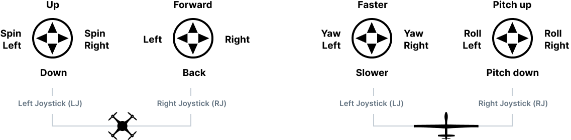
{% hint style="success" %}
If you ever feel that you’re losing control of the vehicle, simply let go of the sticks so that they spring back to the center. A multicopter (or VTOL in MC mode) will hover in place. A vehicle that is flying like a fixed wing will stabilise on its current track and altitude.
{% endhint %}
{% hint style="info" %}
If you’re flying as a VTOL you can switch between the modes by selecting the VTOL transition button in the ground station toolbar.
{% endhint %}
### Step 7: Landing
1. Press the top right button (**RB2 Return mode**) to fly the vehicle back to the launch point and land.
2. Once the vehicle has landed it should disarm after a few seconds. **Do not approach the vehicle until motors stop spinning.**
{% hint style="info" %}
Alternatively you can gently lower the left joystick (in multicopter mode) to land the vehicle.
{% endhint %}
## Next Steps
Skynav is capable of a lot more, including mission planning and execution. More detailed information is available in the ground station user manual: [Auterion Mission Control](/vehicle-operation/auterion-mission-control).
## Troubleshooting
The user manual is the first port of call for any problems. We have also included some troubleshooting guidance below.
| Problem | Suggestions |
| ----------------------------------------------------------------------------- | ------------------------------------------------------------------------------------------------------------------------------------------------------------------------------------------------------------------------------ |
| Unit won’t turn on | Check that the unit is properly charged and that the battery release latch is properly engaged. |
| Pairing doesn’t work | Reboot both Skynav and the vehicle. |
| Aircraft won’t take off | Check errors (refer to Auterion Mission Control guide for more information) |
| The joysticks aren’t detected by the system | Reboot the unit. Check that the Ubuntu application `jstest-gtk` shows the device. |
| The device audio isn’t working in Ubuntu even though the volume is set to max | Reboot the unit and select “Windows Boot Manager” as opposed to "Ubuntu". Once booted and logged into Windows, turn the volume up (any value but 0). Power off and reboot into Ubuntu. |
| I need the battery to last longer | Several functions impact battery life. Try disabling WiFi and Bluetooth, reducing the screen brightness, not using USB accessories, and reducing the integrated radio’s transmit power (this will reduce the effective range). |
| My Skynav doesn’t have enough disk space available | If your Skynav unit is configured for dual boot, there is likely unutilized disk space. Open the partition manager in Windows or Ubuntu (`gparted`) to resize the partition you wish to use primarily. |
{% hint style="info" %}
If you can’t find the answers in the troubleshooting section above or in the user manual, please contact us for help using email: .
{% endhint %}
# Joystick and Button Mapping
Skynav Appendix
The joysticks can be set up in the AMC application. To access the Joystick settings, tap on the Auterion icon in the top left corner, then tap on **"Vehicle Setup"**.
{% hint style="info" %}
Note that a Vehicle or Skynode must be paired and connected in AMC before the Joystick settings and button assignment can be modified.
{% endhint %}

Inside "**Vehicle Setup**" tap on the **"Joystick"** menu as shown in the image below. The "General" tab will list all of the detected joystick and button inputs. Ensure the box "Enable joystick input" is checked. Calibrating the joysticks may be required before enabling the joysticks. This process can be initiated in the "Calibration" tab. Calibration should also be performed if the joystick readings are not centered or drift is noticed during flight.

On the **"Button Assignment"** tab the user can customize the button functions on Skynav, including the 5D pad. The image below is a typical configuration for a drone with a gimbaled camera.

The "Advanced" tab offers further customization options for the Skynav joysticks and buttons. For instance, the stick position that represents zero throttle can be changed, and the shoulder sliders can be enabled or disabled by checking "Enable Gimbal Control". For more information on the Joysticks tab and Advanced features [click here](/vehicle-operation/settings-and-maintenance/joystick-setup).
## QGroundControl
If your Skynav Handheld controller is equipped with QGroundControl rather than Auterion Mission Control, see the open-source for further details.
# Using LTE for Online Maps in the Field
{% hint style="warning" %}
On Skynav booted into Ubuntu, the SIM card is currently not supported.
{% endhint %}
In order to have access to the LTE functionality of your Skynav, you will need an activated SIM card. The SIM card slot is located inside the battery compartment, as shown on the image below:

The current offering for SIM card is the T-Mobile 2GB data plan.
# Advanced Radio Settings
The following is applicable to Skynavs equipped with one of the radios listed below:
* Microhard pDDL1800- 1.8 GHz
* Microhard pMDDL2450 - 2.4 GHz
## Additional Microhard settings in AMC
The "**Pair Vehicle**" button in AMC will typically allow the user to pair the Skynav radio to an air vehicle. Detailed instructions for pairing in AMC can be found in our [Microhard guide](https://github.com/Guscedav/DocsUnited/blob/main/operating-a-vehicle/remote-controllers/skynav/broken-reference/README.md).
AMC also has the ability to change additional Microhard settings. These are found in the "**Settings"** > "**Microhard**" menu as shown below.

For AMC to utilize the Skynav Microhard radio, several fields will be filled out appropriately. If these settings are correct, AMC will list the Ground Unit in green as "*Connected*". The settings required for AMC to recognize the Microhard are:
* Local IP Address (default "192.168.168.1")
* Configuration User Name (default "admin")
* Configuration Password (default "microhard", and "auterionfct" after loading the [auterion configuration](https://github.com/Guscedav/DocsUnited/blob/main/operating-a-vehicle/remote-controllers/skynav/broken-reference/README.md))
If your Skynav unit was shipped with an alternate configuration, this information will be listed in the supplied shipping documents.
The remainder of the radio settings on this page will be applied to the radio connection when in-use. Note that when AMC is in "Pairing Mode", the settings shown above will be overridden with those specified in the pairing menu if they are different, including Encryption Key, Network ID, and Pairing Channel.
## Microhard web UI
{% hint style="info" %}
If changes are made in the Microhard web page such as the IP address, login name, or login password: AMC will need to be updated to reflect these new values. Otherwise, AMC will list the Ground Unit as "Disconnected".
{% endhint %}
* In order to access the advanced radio settings for your particular radio you will need to navigate to the Microhard IP address and enter the correct password
* The IP address of your radio should be **192.168.168.1** unless otherwise specified in your shipping documents.
* Default password
* The default password for your radio is "microhard". This information is also included with you shipment.
* If you would like to change the default password of your Microhard radio, you can do so by navigating to the **Microhard web portal** > **Admin** > **Change Password** and press the Change password button to save your changes.

* **Summary page**
* Once logged into your the Microhard hard web browser you will be able to see the Microhard summary page, with relevant information of the device.

* **Encryption**
* Your Skynav can be configured as **AES128** or **AES256**. To configure your Skynav with either one of the settings, navigate to the **Microhard web portal** > **Wireless** > **RF**
{% hint style="info" %}
When switching back and forth between different encryption types, make sure your aircraft firmware is compatible
{% endhint %}

# Drop Guards and Chest Strap
Skynav Appendix
## Drop Guard Replacements
Drop guard replacements will be included with your Skynav. These can be easily installed by removing the four screws and placing the replacement parts and securing the screws.
## Chest Strap
As part of the optional accessories, we offer a Chest Strap that facilities the use of the Skynav in the field.
Skynav has 4 mounting holes for the chest strap to be installed. Two holes on the bottom edge of the unit and two at the top as shown in the images below.

Once assembled, the chest strap can be snapped into the clips and Skynav can rest comfortably over the shoulder.

# Unit Serial Number
Your Skynav serial number can be found on the back of the unit, right below the model number and it is also located underneath the battery.
# Settings & Maintenance
# Vehicle Setup
The *Vehicle Setup* view is used to configure the vehicle settings that a pilot might *occasionally* need to change before flying.
{% hint style="info" %}
A vehicle must be connected in order to see or modify these settings. If multiple vehicles are connected the setting apply to the currently selected vehicle.
{% endhint %}

The main sections are:
* **Summary:** Overview of all the settings
* [**Sensors**](/hardware-integration/hardware-integration/sensors-setup/compass-calibration)**:** Calibrate sensors and set their orientations
* [**Safety**](/vehicle-operation/settings-and-maintenance/safety)**:** Set the thresholds and actions for various safety failsafes (e.g. low battery)
# WiFi Setup
If you need to connect your vehicle to a network, you can use AMC to do so.
More details in the [documentation](https://docs.auterion.com/vehicle-operation/auterion-mission-control/ui-breakdown/vehicle-overview-menu/connectivity).
# Compass Calibration
The compass calibration process configures all magnetometers on the vehicle.
Calibrate compasses on first use of the vehicle. They should not need to be calibrated again unless exposed to a very strong magnetic field, or if the vehicle is used in an area with abnormal magnetic characteristics.
{% hint style="info" %}
Indications of a poor compass calibration include circling during hover, "toilet bowling" (spiraling-outwards at constant altitude, leading to fly-way), or veering off-path when attempting to fly straight.
{% endhint %}
### Complete 6-sides calibration
{% hint style="info" %}
If the 6-sides magnetometer calibration has already been performed once on the fully assembled drone, follow the steps of the [in-field calibration](#in-field-calibration) section below.
{% endhint %}
*Auterion Mission Control* will guide you to position the vehicle in a number of set orientations and then rotate the vehicle about the specified axis.
{% hint style="warning" %}
Choose a location away from large metal objects or magnetic fields. Metal is not always obvious! Avoid calibrating on top of an office table (often contain metal bars) or next to a vehicle. Calibration can even be affected if you're standing on a slab of concrete with uneven distribution of re-bar.
{% endhint %}
The calibration steps are:
1. Select the **Vehicle Setup** view and then **Sensors > Compass** in the left sidebar.\ \
The Autopilot orientation should already be set correctly for the vehicle.

2. Click **OK** to start the calibration.
3. Place the vehicle in any of the orientations shown in red (incomplete) and hold it still. Once prompted (the orientation-image turns yellow) rotate the vehicle around the specified axis in either/both directions. Once the calibration is complete for the current orientation the associated image on the screen will turn green.

4. Repeat the calibration process for all vehicle orientations.
5. Once you've calibrated the vehicle in all the positions *Mission Control* will display the *Compass Calibration Complete* prompt (all orientation images will be displayed in green and the progress bar will fill completely).\

6. Press **OK** to finish (or **Reboot Vehicle** if the orientation was changed).
### In-field calibration
If the drone shows symptoms of compass issues (e.g.: toilet bowling or pre-flight check error), the sensor biases can be automatically corrected simply by oscillating the drone around its 3 axes by about ±30 degrees. Two oscillations per axis are usually enough to obtain a good result.
Watch the in-field calibration in video below:
{% embed url="" %}
# Safety Setup
The **Vehicle Setup > Safety** page is used to configure the most important failsafe settings.

## Failsafe Actions
Failsafe detection can trigger one of the following (selectable) actions.
| Action | Description |
| -------------------------------- | --------------------------------------------------------------------------------------------------------------------------------------------------------------------------------------------------------------------------------------------------------------- |
| **None/Disabled** | No action (the failsafe will be ignored). |
| **Warning** | A warning message will be displayed/announced. |
| **Hold mode** | The vehicle will enter [Hold mode](https://github.com/Guscedav/DocsUnited/blob/main/operating-a-vehicle/settings-and-maintenance/broken-reference/README.md). For multicopters this means the vehicle will hover, while for fixed/wing the vehicle will circle. |
| **Return mode** | The vehicle will enter [Return mode](https://github.com/Guscedav/DocsUnited/blob/main/operating-a-vehicle/settings-and-maintenance/broken-reference/README.md). Return behaviour can be set in the [Return Home Settings](#return-mode-settings) (below). |
| **Land mode** | The vehicle will enter [Land mode](https://github.com/Guscedav/DocsUnited/blob/main/operating-a-vehicle/settings-and-maintenance/broken-reference/README.md), and land immediately. |
| **CASA Outback Challenge rules** | Unsupported. Do not use. |
| **Flight termination** | Turns off all controllers and sets all PWM outputs to their failsafe values. The failsafe outputs can be used to deploy a parachute, landing gear or perform another operation. |
| **Lockdown** | Kills the motors (sets them to disarmed). This is the same as using the kill switch. |
{% hint style="info" %}
It is possible to recover from a failsafe action (if the cause is fixed) by switching modes. For example, in the case where RC Loss failsafe causes the vehicle to enter Return mode, if RC is recovered you can change to Position mode and continue flying.
{% endhint %}
{% hint style="info" %}
If a failsafe occurs while the vehicle is responding to another failsafe (e.g. Low battery while in Return mode due to RC Loss), the specified failsafe action for the second trigger is ignored. Instead the action is determined by separate system level and vehicle specific code. This might result in the vehicle being changed to a manual mode so the user can directly manage recovery.
{% endhint %}
## Low Battery

The l\_ow battery failsafe\_ is triggered when the battery capacity drops below one (or more warning) level values.
The most common configuration is to set the action at *Return mode at critically low level, land mode at current position if reaching dangerously low levels* and the levels with `Warn > Failsafe > Emergency`. With this configuration the failsafe will trigger warning, then return, and finally landing as the capacity drops below the respective levels.
Alternatively set the *Failsafe Action* to warn, return, or land when the **Battery Failsafe Level** level is reached.
| Setting | Description |
| --------------------------- | ------------------------------------------------------------------------------------------------------------------------------------------------------------------------------------------------------------------------------------------------------------------------------------------------------------------------------------------------------------------------------------------------------------------------------------------------------------------------------------------------------------------------------ |
| **Failsafe Action** |
Return Mode. Return mode and warn if capacity drops below Battery Failsafe Level.
Land Mode. Land mode and warn if capacity drops below Battery Failsafe Level.
Return mode at critically low level, land mode at current position if reaching dangerously low levels. Triggers warning, return mode and land mode at the respective levels.
|
| **Battery Warn Level** | Percentage capacity for Warnings (if Warning action enabled). |
| **Battery Failsafe Level** | Percentage capacity for Return Mode action (if enabled). |
| **Battery Emergency Level** | Percentage capacity for Land Mode action (if enabled). |
## Object Detection

Enable/disable collision prevention and obstacle avoidance, and set the closest approach distance allowed when collision prevention is active.
| Setting | Description |
| ------------------------ | ------------------------------------------------------------------------------------------------ |
| **Collision Prevention** | Disabled/Enabled. |
| **Obstacle Avoidance** | Disabled/Enabled. |
| **Minimum Distance** | Distance (metres) away from obstacle that vehicle will stop when collision prevention is active. |
## RC Loss

Set the action on RC loss, and how quickly the vehicle responds.
| Setting | Description |
| ------------------- | --------------------------------------------------------------------------------------------------------------------------------------- |
| **Failsafe Action** | Values are: *Disabled*, Hold mode, Return mode, Land mode, Data Link Auto Recovery (CASA Outback Challenge rules), Terminate, Lockdown. |
| **RC Loss Timeout** | Time after RC loss that the *Failsafe Action* is triggered. |
## Data Link Loss

Set the action on data-link loss (loss of telemetry to ground station), and how quickly the vehicle responds.
| Setting | Description |
| -------------------------- | --------------------------------------------------------------------------------------------------------------------------------------------------- |
| **Failsafe Action** | Values are: *Disabled*, *Hold mode*, *Return mode*, *Land mode*, *Data Link Auto Recovery (CASA Outback Challenge rules)*, *Terminate*, *Lockdown*. |
| **Data Link Loss Timeout** | Time after data link loss that the *Failsafe Action* is triggered. |
## Geofence Failsafe

The *Geofence Failsafe* is a "virtual" cylinder centered around the home position. If the flight controller detects a situation where the vehicle is on a trajectory to move outside of the cylinder (an "impending breach"), then the specified [Failsafe Action ](#failsafe-actions)will trigger.
{% hint style="info" %}
*Auterion Mission Control* supports more complicated GeoFence geometries with multiple arbitrary polygonal and circular inclusion and exclusion areas in: [Planning > GeoFence](/vehicle-operation/auterion-mission-control/ui-breakdown/plan/geofence-plan).
{% endhint %}
Set the action on impending fence breach, and the radius and/or altitude of the geofence cylinder.
| Setting | Description |
| -------------------------------- | -------------------------------------------------------------------------- |
| **Action on (Impending) Breach** | Values are: none, *Warning*, \_Hold mod\_e, *Return mode*, *Terminate*. |
| **Max Radius** | Horizontal radius of geofence cylinder. Horizontal geofence disabled if 0. |
| **Max Altitude** | Height of geofence cylinder. Altitude geofence disabled if 0. |
{% hint style="info" %}
If the [Hold mode](https://github.com/Guscedav/DocsUnited/blob/main/operating-a-vehicle/settings-and-maintenance/broken-reference/README.md) action is set then the hold location is positioned such that it will not cause a geofence violation. For fixed wings this means that the center of the loiter circle is set more than the loiter radius away from the geofence boundary.
{% endhint %}
{% hint style="info" %}
If [Return mode](https://github.com/Guscedav/DocsUnited/blob/main/operating-a-vehicle/settings-and-maintenance/broken-reference/README.md) action is set then there is no guarantee that the vehicle will not violate any geofence on its return path.
{% endhint %}
## Return Mode Settings
{% hint style="info" %}
Generally return mode settings will be pre-configured by the supplier of the vehicle. The mode may be configured to use a return destination that is not affected by these settings.
{% endhint %}

[Return mode](https://github.com/Guscedav/DocsUnited/blob/main/operating-a-vehicle/settings-and-maintenance/broken-reference/README.md) causes a vehicle to fly at a safe height to a safe destination, where it may loiter and/or then land. This section allows the return height, and landing behaviour to be specified for rally point and home location landings.
| Setting | Description |
| ------------------------ | ------------------------------------------------------------------------------------------------------ |
| **Climb to altitude of** | Vehicle ascend to this minimum height (if below it) for the return flight. |
| **Return home then** | The action on return: Land, Loiter and do not land, or Loiter and land after a specified time. |
| **Loiter Time** | The time to loiter before landing (if return home action is *Loiter and land after a specified time*). |
| **Loiter Altitude** | Altitude at which the vehicle will loiter (i.e. before landing). |
## Land Mode Settings

Specify Land mode descent and disarm behaviour.
| Setting | Description |
| ------------------------ | ---------------------------------------------------------------------------------------------------------------------------------------------------------------------- |
| **Landing Descent Rate** | Land descent rate. |
| **Disarm After** | Auto disarm vehicle on landing (the default) by enabling the checkbox and setting the disarm time. If checkbox not enabled, the vehicle will not disarm after landing. |
## Vehicle Telemetry Logging

Enable telemetry logging to vehicle storage.
| Setting | Description |
| ---------------------------------------- | ------------------------ |
| **Telemetry logging to vehicle storage** | Enabled/Disable logging. |
## Hardware In The Loop Simulation (HITL)
{% hint style="info" %}
Pilots should not change this setting.
{% endhint %}

Enable hardware-dependent simulation: *hardware in the loop* or *simulation in hardware*.
| Setting | Description |
| ---------------- | ------------------------------------------------------------------------------------------------------------------------------------------------------------------------------------------------------------------------------------ |
| **HITL Enabled** |
Values:
HITL and SIH disabled: Hardware-dependent simulation disabled.
.jpg) \
The Autopilot orientation should already be set correctly for the vehicle.

2. Click **OK** to start the calibration.
3. Place the vehicle in any of the orientations shown in red (incomplete) and hold it still. Once prompted (the orientation-image turns yellow) rotate the vehicle around the specified axis in either/both directions. Once the calibration is complete for the current orientation the associated image on the screen will turn green.

4. Repeat the calibration process for all vehicle orientations.
5. Once you've calibrated the vehicle in all the positions *Mission Control* will display the *Compass Calibration Complete* prompt (all orientation images will be displayed in green and the progress bar will fill completely).\

6. Press **OK** to finish (or **Reboot Vehicle** if the orientation was changed).
### In-field calibration
If the drone shows symptoms of compass issues (e.g.: toilet bowling or pre-flight check error), the sensor biases can be automatically corrected simply by oscillating the drone around its 3 axes by about ±30 degrees. Two oscillations per axis are usually enough to obtain a good result.
Watch the in-field calibration in video below:
{% embed url="
\
The Autopilot orientation should already be set correctly for the vehicle.

2. Click **OK** to start the calibration.
3. Place the vehicle in any of the orientations shown in red (incomplete) and hold it still. Once prompted (the orientation-image turns yellow) rotate the vehicle around the specified axis in either/both directions. Once the calibration is complete for the current orientation the associated image on the screen will turn green.

4. Repeat the calibration process for all vehicle orientations.
5. Once you've calibrated the vehicle in all the positions *Mission Control* will display the *Compass Calibration Complete* prompt (all orientation images will be displayed in green and the progress bar will fill completely).\

6. Press **OK** to finish (or **Reboot Vehicle** if the orientation was changed).
### In-field calibration
If the drone shows symptoms of compass issues (e.g.: toilet bowling or pre-flight check error), the sensor biases can be automatically corrected simply by oscillating the drone around its 3 axes by about ±30 degrees. Two oscillations per axis are usually enough to obtain a good result.
Watch the in-field calibration in video below:
{% embed url="